Definition
Power is a physical quantity that is used as the main characteristic of any device that is used to perform work. Net power can be used to complete the task.
The ratio of work ($\Delta A$) to the period of time during which it was completed ($\Delta t$) is called the average power ($\left\langle P\right\rangle $) for this time:
\[\left\langle P\right\rangle =\frac(\Delta A)(\Delta t)\left(1\right).\]
Instantaneous power, or more often simply power, is the limit of relation (1) at $\Delta t\to 0$:
Taking into account that:
\[\Delta A=\overline(F)\cdot \Delta \overline(r\ )\left(3\right),\]
where $\Delta \overline(r\ )$ is the movement of the body under the action of force $\overline(F)$, in expression (2) we have:
where $\ \overline(v)-$ is the instantaneous speed.
Efficiency
When performing necessary (useful) work, for example, mechanical work, it is necessary to perform a larger amount of work, since in reality there are resistance forces and part of the energy is subject to dissipation (dissipation). The efficiency of work is determined using the efficiency factor ($\eta $), while:
\[\eta =\frac(P_p)(P)\left(5\right),\]
where $P_p$ is useful power; $P$ - consumed power. From expression (5) it follows that the useful power can be found as:
Formula for useful power of current source
Let the electrical circuit consist of a current source having resistance $r$ and a load (resistance $R$). We find the power of the source as:
where $?$ is the EMF of the current source; $I$ - current strength. In this case, $P$ is the total power of the circuit.
Let's denote $U$ - the voltage on the external section of the circuit, then formula (7) will be presented in the form:
where $P_p=UI=I^2R=\frac(U^2)(R)(9)$ - useful power; $P_0=I^2r$ - loss power. In this case, the source efficiency is determined as:
\[\eta =\frac(P_p)(P_p+P_0)\left(9\right).\]
The maximum useful power (power at the load) is produced by the electric current if the external resistance of the circuit is equal to the internal resistance of the current source. Under this condition, the useful power is equal to 50\% of the total power.
During a short circuit (when $R\to 0;;U\to 0$) or in idle mode $(R\to \infty ;;I\to 0$) the useful power is zero.
Examples of problems with solutions
Example 1
Exercise. The efficiency of the electric motor is $\eta $ =42%. What will be its useful power if at a voltage of $U=$110 V a current of $I=$10 A flows through the motor?
Solution. As a basis for solving the problem, we take the formula:
We find the total power using the expression:
Substituting the right side of expression (1.2) into (1.1) we find that:
Let's calculate the required power:
Answer.$P_p=462$ W
Example 2
Exercise. What is the maximum useful power of the current source if its short circuit current is equal to $I_k$? When connected to a resistance current source $R$, a current of force $I$ flows through the circuit (Fig. 1).
Solution. According to Ohm's law, for a circuit with a current source we have:
where $\varepsilon$ is the EMF of the current source; $r$ is its internal resistance.
In case of a short circuit, we assume that the resistance of the external load is zero ($R=0$), then the short circuit current is equal to:
The maximum useful power in the circuit Fig. 1 will give electric current, provided:
Then the current in the circuit is equal to:
We find the maximum useful power using the formula:
We received a system of three equations with three unknowns:
\[\left\( \begin(array)(c) I"=\frac(\varepsilon)(2r), \\ I_k=\frac(\varepsilon)(r), \\ P_(p\ max)= (\left(I"\right))^2r \end(array) \left(2.6\right).\right.\]
Using the first and second equations of system (2.6) we find $I"$:
\[\frac(I")(I_k)=\frac(\varepsilon)(2r)\cdot \frac(r)(\varepsilon)=\frac(1)(2)\to I"=\frac(1 )(2)I_k\left(2.7\right).\]
We use equations (2.1) and (2.2) to express the internal resistance of the current source:
\[\varepsilon=I\left(R+r\right);;\ I_kr=\varepsilon \to I\left(R+r\right)=I_kr\to r\left(I_k+I\right)=IR \to r=\frac(IR)(I_k-I)\left(2.8\right).\]
Let us substitute the results from (2.7) and (2.8) into the third formula of system (2.6), the required power will be equal to:
Answer.$P_(p\ max)=(\left(\frac(1)(2)I_k\right))^2\frac(IR)(I_k-I)$
When connecting electrical appliances to the electrical network, only the power and efficiency of the electrical appliance itself usually matters. But when using a current source in a closed circuit, the useful power it produces is important. The source can be a generator, accumulator, battery or elements of a solar power plant. This is not of fundamental importance for calculations.
Power supply parameters
When connecting electrical appliances to the power supply and creating a closed circuit, in addition to the energy P consumed by the load, the following parameters are taken into account:
- Rob. (total power of the current source) released in all sections of the circuit;
- EMF is the voltage generated by the battery;
- P (net power) consumed by all sections of the network, except the current source;
- Po (loss power) spent inside the battery or generator;
- internal resistance of the battery;
- Efficiency of the power supply.
Attention! The efficiency of the source and the load should not be confused. If the battery coefficient in an electrical appliance is high, it may be low due to losses in the wires or the device itself, and vice versa.
More about this.
Total circuit energy
When electric current passes through a circuit, heat is generated or other work is performed. A battery or generator is no exception. The energy released on all elements, including wires, is called total. It is calculated using the formula Rob.=Ro.+Rpol., where:
- Rob. - full power;
- Ro. – internal losses;
- Rpol. – useful power.

Attention! The concept of apparent power is used not only in calculations of a complete circuit, but also in calculations of electric motors and other devices that consume reactive energy along with active energy.
EMF, or electromotive force, is the voltage generated by a source. It can only be measured in X.X mode. (idle move). When a load is connected and current appears, Uо is subtracted from the EMF value. – voltage loss inside the power supply device.

Net power
Useful is the energy released in the entire circuit, except for the power supply. It is calculated by the formula:
- “U” – voltage at terminals,
- “I” – current in the circuit.
In a situation in which the load resistance is equal to the resistance of the current source, it is maximum and equal to 50% of the full value.
As the load resistance decreases, the current in the circuit increases along with internal losses, and the voltage continues to fall, and when it reaches zero, the current will be maximum and limited only by Ro. This is K.Z mode. - short circuit. In this case, the loss energy is equal to the total.
As the load resistance increases, the current and internal losses fall, and the voltage rises. When reaching an infinitely large value (network break) and I=0, the voltage will be equal to the EMF. This is X..X mode. - idle move.
Losses inside the power supply
Batteries, generators and other devices have internal resistance. When current flows through them, loss energy is released. It is calculated using the formula:
where “Uо” is the voltage drop inside the device or the difference between the EMF and the output voltage.
Internal power supply resistance
To calculate losses Ro. you need to know the internal resistance of the device. This is the resistance of the generator windings, the electrolyte in the battery or for other reasons. It is not always possible to measure it with a multimeter. We have to use indirect methods:
- when the device is turned on in idle mode, E (EMF) is measured;
- when the load is connected, Uout is determined. (output voltage) and current I;
- The voltage drop inside the device is calculated:
- internal resistance is calculated:
Useful energy P and efficiency
Depending on the specific tasks, maximum useful power P or maximum efficiency is required. The conditions for this do not match:
- P is maximum at R=Ro, with efficiency = 50%;
- Efficiency is 100% in H.H. mode, with P = 0.

Obtaining maximum energy at the output of the power supply device
Maximum P is achieved provided that the resistances R (load) and Ro (electricity source) are equal. In this case, efficiency = 50%. This is the “matched load” mode.
Apart from this, two options are possible:
- Resistance R drops, the current in the circuit increases, and the voltage losses Uo and Po inside the device increase. In short circuit mode (short circuit) the load resistance is “0”, I and Po are maximum, and the efficiency is also 0%. This mode is dangerous for batteries and generators, so it is not used. The exception is welding generators and car batteries that are practically out of use, which, when starting the engine and turning on the starter, operate in a mode close to “short circuit”;
- The load resistance is greater than the internal one. In this case, the load current and power P drop, and with an infinitely large resistance they are equal to “0”. This is X.H. mode. (idle move). Internal losses in the near-C.H. mode are very small, and the efficiency is close to 100%.
Consequently, “P” is maximum when the internal and external resistances are equal and is minimal in other cases due to high internal losses during short circuit and low current in the cold mode.
The maximum net power mode at 50% efficiency is used in electronics at low currents. For example, in a telephone set Pout. microphone - 2 milliwatts, and it is important to transfer it to the network as much as possible, while sacrificing efficiency.
Achieving maximum efficiency
Maximum efficiency is achieved in the H.H. mode. due to the absence of power losses inside the Po voltage source. As the load current increases, the efficiency decreases linearly in short-circuit mode. is equal to “0”. The maximum efficiency mode is used in power plant generators where matched load, maximum useful Po and 50% efficiency are not applicable due to large losses, accounting for half of the total energy.
Load efficiency
The efficiency of electrical appliances does not depend on the battery and never reaches 100%. The exception is air conditioners and refrigerators that operate on the principle of a heat pump: cooling one radiator occurs by heating the other. If you do not take this point into account, the efficiency will be above 100%.
Energy is spent not only on performing useful work, but also on heating wires, friction and other types of losses. In lamps, in addition to the efficiency of the lamp itself, you should pay attention to the design of the reflector, in air heaters - on the efficiency of heating the room, and in electric motors - on cos φ.
Knowing the useful power of the power supply element is necessary to perform calculations. Without this, it is impossible to achieve maximum efficiency of the entire system.
Video
The power developed by the current source in the entire circuit is called full power.
It is determined by the formula
where P rev is the total power developed by the current source in the entire circuit, W;
E-uh. d.s. source, in;
I is the magnitude of the current in the circuit, a.
In general, an electrical circuit consists of an external section (load) with resistance R and internal section with resistance R0(resistance of the current source).

Replacing the value of e in the expression for total power. d.s. through the voltages on the sections of the circuit, we get
Magnitude UI corresponds to the power developed on the external section of the circuit (load), and is called useful power P floor =UI.
Magnitude U o I corresponds to the power uselessly spent inside the source, It is called loss power P o =U o I.
Thus, the total power is equal to the sum of the useful power and the loss power P ob =P floor +P 0.
The ratio of useful power to the total power developed by the source is called efficiency, abbreviated as efficiency, and is denoted by η.
From the definition it follows

Under any conditions, efficiency η ≤ 1.
If we express the power in terms of the current and resistance of the circuit sections, we get

Thus, efficiency depends on the relationship between the internal resistance of the source and the resistance of the consumer.
Typically, electrical efficiency is expressed as a percentage.

For practical electrical engineering, two questions are of particular interest:
1. Condition for obtaining the greatest useful power
2. Condition for obtaining the highest efficiency.
Condition for obtaining the greatest useful power (power in load)
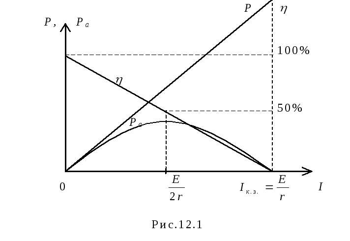
The electric current develops the greatest useful power (power at the load) if the load resistance is equal to the resistance of the current source.
This maximum power is equal to half of the total power (50%) developed by the current source in the entire circuit.
Half of the power is developed at the load and half is developed at the internal resistance of the current source.
If we reduce the load resistance, then the power developed at the load will decrease and the power developed at the internal resistance of the current source will increase.
If the load resistance is zero then the current in the circuit will be maximum, this is short circuit mode (short circuit) . Almost all the power will be developed at the internal resistance of the current source. This mode is dangerous for the current source and also for the entire circuit.
If we increase the load resistance, the current in the circuit will decrease, and the power on the load will also decrease. If the load resistance is very high, there will be no current in the circuit at all. This resistance is called infinitely large. If the circuit is open, its resistance is infinitely large. This mode is called idle mode.
Thus, in modes close to a short circuit and no-load, the useful power is small in the first case due to the low voltage, and in the second due to the low current.
Condition for obtaining the highest efficiency
The efficiency factor (efficiency) is 100% at idle (in this case, no useful power is released, but at the same time, the source power is not consumed).
As the load current increases, efficiency decreases according to a linear law.
In short-circuit mode, the efficiency is zero (there is no useful power, and the power developed by the source is completely consumed within it).
Summarizing the above, we can draw conclusions.
The condition for obtaining maximum useful power (R = R 0) and the condition for obtaining maximum efficiency (R = ∞) do not coincide. Moreover, when receiving maximum useful power from the source (matched load mode), the efficiency is 50%, i.e. half of the power developed by the source is wasted inside it.
In powerful electrical installations, the matched load mode is unacceptable, since this results in a wasteful expenditure of large powers. Therefore, for electrical stations and substations, the operating modes of generators, transformers, and rectifiers are calculated so as to ensure high efficiency (90% or more).
The situation is different in weak current technology. Let's take, for example, a telephone set. When speaking in front of a microphone, an electrical signal with a power of about 2 mW is created in the device’s circuitry. Obviously, in order to obtain the greatest communication range, it is necessary to transmit as much power as possible into the line, and this requires a coordinated load switching mode. Does efficiency matter in this case? Of course not, since energy losses are calculated in fractions or units of milliwatts.
The matched load mode is used in radio equipment. In the case where a coordinated mode is not ensured when the generator and load are directly connected, measures are taken to match their resistances.
There are two types of elements in an electrical or electronic circuit: passive and active. The active element is capable of continuously supplying energy to the circuit - battery, generator. Passive elements - resistors, capacitors, inductors, only consume energy.
What is a current source
A current source is a device that continuously supplies a circuit with electricity. It can be a source of direct current and alternating current. Batteries are sources of direct current, and electrical outlets are sources of alternating current.
One of the most interesting characteristics of power sources– they are capable of converting non-electrical energy into electrical energy, for example:
- chemical in batteries;
- mechanical in generators;
- solar, etc.
Electrical sources are divided into:
- Independent;
- Dependent (controlled), the output of which depends on the voltage or current elsewhere in the circuit, which can be either constant or varying with time. Used as equivalent power supplies for electronic devices.
When talking about circuit laws and analysis, electrical power supplies are often considered ideal, that is, theoretically capable of providing an infinite amount of energy without loss, while having characteristics represented by a straight line. However, in real or practical sources there is always internal resistance that affects their output.
Important! SPs can be connected in parallel only if they have the same voltage value. The series connection will affect the output voltage.

The internal resistance of the power supply is represented as being connected in series with the circuit.
Current source power and internal resistance
Let us consider a simple circuit in which the battery has an emf E and an internal resistance r and supplies a current I to an external resistor with a resistance R. The external resistor can be any active load. The main purpose of the circuit is to transfer energy from the battery to the load, where it does something useful, such as lighting a room.
You can derive the dependence of useful power on resistance:
- The equivalent resistance of the circuit is R + r (since the load resistance is connected in series with the external load);
- The current flowing in the circuit will be determined by the expression:
- EMF output power:
Rych. = E x I = E²/(R + r);
- Power dissipated as heat at internal battery resistance:
Pr = I² x r = E² x r/(R + r)²;
- Power transmitted to load:
P(R) = I² x R = E² x R/(R + r)²;
- Rych. = Pr + P(R).
Thus, part of the battery's output energy is immediately lost due to heat dissipation through the internal resistance.
Now you can plot the dependence of P(R) on R and find out at what load the useful power will take its maximum value. When analyzing the function for an extremum, it turns out that as R increases, P(R) will monotonically increase until the point where R does not equal r. At this point, the useful power will be maximum, and then begins to decrease monotonically with further increase in R.
P(R)max = E²/4r, when R = r. In this case, I = E/2r.
Important! This is a very significant result in electrical engineering. Transfer of energy between the power source and the external load is most efficient when the load resistance matches the internal resistance of the current source.
If the load resistance is too high, then the current flowing through the circuit is small enough to transfer energy to the load at an appreciable rate. If the load resistance is too low, then most of the output energy is dissipated as heat within the power supply itself.

This condition is called coordination. One example of matching source impedance and external load is an audio amplifier and loudspeaker. The amplifier's output impedance Zout is set from 4 to 8 ohms, while the speaker's nominal input impedance Zin is only 8 ohms. Then, if an 8 ohm speaker is connected to the amplifier's output, it will see the speaker as an 8 ohm load. Connecting two 8 ohm speakers in parallel with each other is equivalent to an amplifier driving a single 4 ohm speaker, and both configurations are within the amplifier's output characteristics.
Current source efficiency
When work is done by electric current, energy transformations occur. The full work done by the source goes to energy transformations throughout the entire electrical circuit, and the useful work only in the circuit connected to the power source.
Quantitative assessment of the efficiency of the current source is made according to the most significant indicator that determines the speed of work, – power:
Not all of the output power of the IP is used by the energy consumer. The ratio of energy consumed and energy supplied by the source is the efficiency formula:
η = useful power/output power = Ppol./Pout.
Important! Since Ppol. in almost any case less than Pout, η cannot be greater than 1.

This formula can be transformed by substituting expressions for powers:
- Source output power:
Rych. = I x E = I² x (R + r) x t;
- Energy consumed:
Rpol. = I x U = I² x R x t;
- Coefficient:
η = Ppol./Pout. = (I² x R x t)/(I² x (R + r) x t) = R/(R + r).
That is, the efficiency of a current source is determined by the ratio of resistances: internal and load.
Often the efficiency indicator is used as a percentage. Then the formula will take the form:
η = R/(R + r) x 100%.
From the resulting expression it is clear that if the matching condition is met (R = r), the coefficient η = (R/2 x R) x 100% = 50%. When the transmitted energy is most efficient, the efficiency of the power supply itself is only 50%.
Using this coefficient, the efficiency of various individual entrepreneurs and electricity consumers is assessed.
Examples of efficiency values:
- gas turbine – 40%;
- solar battery – 15-20%;
- lithium-ion battery – 89-90%;
- electric heater – close to 100%;
- incandescent lamp – 5-10%;
- LED lamp – 5-50%;
- refrigeration units – 20-50%.
Indicators of useful power are calculated for different consumers depending on the type of work performed.
Video
 (12.11)
A short circuit is a circuit operating mode in which the external resistance R= 0. At the same time
 (12.12)
Net power R A = 0.
Full power
 (12.13)
Dependency graph R A (I) is a parabola, the branches of which are directed downwards (Fig. 12.1). The same figure shows the dependence of the efficiency on the current strength.
Examples of problem solving
Task 1. The battery consists of n= 5 elements connected in series with E= 1.4 V and internal resistance r= 0.3 Ohm each. At what current is the useful power of the battery equal to 8 W? What is the maximum usable power of the battery?
Given: Solution
n = 5 When connecting elements in series, the current in the circuit
E= 1.4 V  (1)
(1)
R A= 8 W From the useful power formula  let's express
external resistance R and substitute into formula (1)
I
-
?
 -?
-? 
after transformations we obtain a quadratic equation, solving which we find the value of the currents:


 A; I 2
=
A; I 2
=
 A.
A.
So, at currents I 1 and I 2 the useful power is the same. When analyzing the graph of the dependence of useful power on current, it is clear that when I 1 less power loss and higher efficiency.
Net power is maximum at R
=
n
r;
R
= 0,3 Ohm.
Ohm.


Answer:
I 1 = 2 A; I 2
=
 A; P amax =
  Tue
Tue
Task 2. The useful power released in the external part of the circuit reaches a maximum value of 5 W at a current of 5 A. Find the internal resistance and emf of the current source.
Given: Solution
P amax = 5 W Useful power  (1)
(1)
I= 5 A according to Ohm's law  (2)
(2)
Net power is maximum at R = r, then from
r
- ? E- ? formulas (1)  0.2 Ohm.
From formula (2) B.
Answer: r= 0.2 Ohm; E= 2 V.
Task 3. A generator with an EMF of 110V is required to transmit energy over a distance of 2.5 km via a two-wire line. Power consumption is 10 kW. Find the minimum cross-section of copper supply wires if power losses in the network should not exceed 1%.
Given: Solution
E = 110V Wire Resistance 
l= 510 3 m where - resistivity of copper; l– length of wires;
R A = 10 4 W S– section.
= 1.710 -8 Ohm. m Power consumption P a = I E, power lost
R etc = 100 W online P etc = I 2 R etc, and since in breeding and consumer
S - ? current the same, then

where 
Substituting the numerical values, we get
 m 2.
m 2.
Answer: S= 710 -3 m 2.
Task 4. Find the internal resistance of the generator if it is known that the power released in the external circuit is the same for two values of external resistance R 1 = 5 ohms and R 2 = 0.2 Ohm. Find the generator efficiency in each of these cases.
Given: Solution
R 1 = R 2 The power released in the external circuit is P a = I 2 R. According to Ohm's law
R 1 = 5 ohms for closed circuit  Then
Then  .
.
R 2 = 0.2 Ohm Using the problem condition R 1 = R 2, we get
r
-?


Transforming the resulting equality, we find the internal resistance of the source r:
 Ohm.
Ohm.
The efficiency factor is the quantity
 ,
,
Where R A– power released in the external circuit; R- full power.
Answer:
r= 1 Ohm;  =
83 %;
=
83 %; =
17 %.
=
17 %.
Task 5. EMF of battery E= 16 V, internal resistance r= 3 Ohm. Find the resistance of the external circuit if it is known that power is released in it R A= 16 W. Determine the efficiency of the battery.
Given: Solution
E= 16 V Power released in the external part of the circuit R A = I 2 R.
r
=
3 Ohm We find the current strength using Ohm's law for a closed circuit: 
R A= 16 W then  or
or 
- ? R- ? We substitute the numerical values of the given quantities into this quadratic equation and solve it for R:
Ohm; R 2 = 9 ohms.
Answer: R 1 = 1 ohm; R 2 = 9 Ohm;
Task 6. Two light bulbs are connected to the network in parallel. The resistance of the first bulb is 360 Ohms, the resistance of the second is 240 Ohms. Which light bulb absorbs the most power? How many times?
Given: Solution
R 1 = 360 Ohm The power released in the light bulb is
R 2 = 240 Ohm P = I 2 R (1)
 -
?
With a parallel connection, the light bulbs will have the same voltage, so it’s better to compare powers by transforming formula (1) using Ohm’s law
-
?
With a parallel connection, the light bulbs will have the same voltage, so it’s better to compare powers by transforming formula (1) using Ohm’s law  Then
Then 

When bulbs are connected in parallel, more power is released into the bulb with lower resistance.
Answer:

Task 7. Two consumers with resistances R 1 = 2 ohms and R 2 = 4 Ohms are connected to the DC network the first time in parallel, and the second time in series. In what case is more power consumed from the network? Consider the case when R 1 = R 2 .
Given: Solution
R 1 = 2 Ohm Power consumption from the network
R 2 = 4 ohms  (1)
(1)
 -
?
Where R– general consumer resistance; U– network voltage. When connecting consumers in parallel, their total resistance
-
?
Where R– general consumer resistance; U– network voltage. When connecting consumers in parallel, their total resistance  and with sequential R
= R 1
+ R 2 .
and with sequential R
= R 1
+ R 2 .
In the first case, according to formula (1), the power consumption  and in the second
  where
where 
Thus, when loads are connected in parallel, more power is consumed from the network than when connected in series.
At 
Answer:

Task 8.. The boiler heater consists of four sections, the resistance of each section is R= 1 Ohm. The heater is powered by a battery with E = 8 V and internal resistance r= 1 Ohm. How should the heater elements be connected so that the water in the boiler heats up in the shortest possible time? What is the total power consumed by the battery and its efficiency?
Given:
R 1 = 1 ohm
E = 8 V
r= 1 Ohm

Solution
The source provides maximum useful power if the external resistance R equal to internal r.
Therefore, in order for the water to heat up in the shortest possible time, the sections need to be turned on so
to R = r. This condition is met with a mixed connection of sections (Fig. 12.2.a, b).
The power consumed by the battery is R
= I
E. According to Ohm's law for a closed circuit  Then
Then 
Let's calculate  32 W;
32 W; 
Answer: R= 32 W; = 50 %.
Problem 9*. Current in a conductor with resistance R= 12 Ohm decreases uniformly from I 0 = 5 A to zero over time = 10 s. How much heat is released in the conductor during this time?
Given:
R= 12 Ohm
I 0 = 5 A
Q - ?
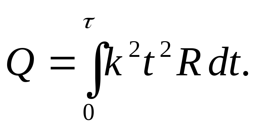
SolutionSince the current strength in the conductor changes, to calculate the amount of heat using the formula Q = I 2 R t cannot be used.
Let's take the differential dQ
=
I
2 R
dt, Then  Due to the uniformity of the current change, we can write I
=
k
t, Where k– proportionality coefficient.
Due to the uniformity of the current change, we can write I
=
k
t, Where k– proportionality coefficient.
Proportionality factor value k we find from the condition that when
= 10 s current I 0 = 5 A, I 0
= k
, from here 

Let's substitute the numerical values:
 J.
J.
Answer: Q= 1000 J.