Fire detectors. 2. Fire control panel. 3. Fire control device.
Actuator drive. 5. State indicator (sensor). 6. Actuator.
Typical block diagram of a control panel and control device with a radial structure
Fire detectors. 2. Fire control panel. 3. Fire control device
Typical block diagram of an addressable control panel and control device with a ring structure
Fire detectors. 2. Fire control panel. 3. Fire control device. 4. Line insulator. 5. Actuator drive.
Regulatory documents defining technical requirements for security and fire automatic equipment, test methods and applications
SNiP 2.04.09-84. Fire automatics of buildings and structures.
SNiP 3.05.06-85. Electrical devices.
SNiP 3.05.07-85. Automation system.
CH 364-67. Instructions for the design of enterprises and facilities constructed on the basis of complex imported equipment and equipment manufactured under license.
VSN 60-93. Communication devices, signaling and dispatching of engineering equipment of residential and public buildings. Design standards.
PUE-76 Rules for electrical installations. SectionVII. Electrical equipment for special installations
GOST 12997-84 GSP products. General technical conditions.
GOST 15150-69 Machines, instruments and other technical products. Versions for different climatic regions. Categories, conditions of operation, storage and transportation in terms of the impact of environmental climatic factors.
GOST 17516.1-90 Electrical products. General requirements regarding resistance to mechanical external influences.
GOST 22522-91 Radioisotope fire detectors. General technical requirements. Test methods.
GOST 27990-88 Security, fire and security and fire alarm system. General technical requirements.
GOST 26342-84 Security, fire and security-fire alarm systems. Types, main parameters and sizes.
GOSTP 51089-97 Fire alarm and control devices. General technical requirements. Test methods.
GOSTP 50658-94 Systems alarm system. Part 2. Requirements for the security alarm system. Section 4. Ultrasonic Doppler detectors for enclosed spaces.
GOSTP 50659-94 Alarm systems. Part 2. Requirements for the security alarm system. Section 5. Radio wave Doppler detectors for enclosed spaces.
GOSTP 50775-95 Alarm systems. Part 1. General requirements. Section 1. General provisions.
GOSTP 50777-95 Alarm systems. Part 2. Requirements for the security alarm system. Section 6. Passive optoelectronic security detectors for enclosed spaces
GOSTP 50898-96 Fire detectors. Fire tests.
GOSTP 50009-92 Compatibility of technical means of security, fire and security-fire alarms is electromagnetic. Requirements, standards and test methods for noise immunity and industrial interference.
GOST 12.2.006-87 Safety of electronic network equipment and similar devices intended for household and similar general use.
GOST R 50898-96 Fire detectors. Fire tests.
GOST 12.2.003-91. SSBT. Production equipment. General safety requirements.
GOST 12.2.007.0-75. SSBT. Electrical products. General safety requirements.
GOST 12.2.020-76. SSBT. Electrical equipment is explosion-proof. Classification. Marking.
GOST 27.003-90. Reliability in technology. Composition and general rules setting reliability requirements.
GOST 14254-80 (IEC 529-76). Electrical products. Shells. Degrees of protection. Notation. Test methods.
GOST 22782.0-81. Electrical equipment is explosion-proof. General technical requirements and test methods.
GOST 23611-79. Electromagnetic compatibility of radio-electronic equipment.
OST 16 0.614.012-73. Explosion-proof electrical equipment. Output currents.
OST 25 1240-86. Instruments and automation equipment. Reliability. Control test methods.
GOST 4.188-85. SPKP. Security, fire and security-fire alarm systems. Nomenclature of indicators.
NPB 65-97 Optoelectronic smoke fire detectors. General technical requirements. Test methods.
NPB 66-97 Autonomous fire detectors. General technical requirements. Test methods.
NPB 57-98 Instruments and equipment for automatic fire extinguishing and fire alarm systems. Noise immunity and noise emission. General technical requirements. Test methods.
NPB 58-97 Addressable fire alarm systems General technical requirements. Test methods.
NPB 70-98 Manual fire detectors. General technical requirements. Test methods.
NPB 71-98 Gas fire detectors. General technical requirements. Test methods.
NPB 72-98 Fire flame detectors. General technical requirements. Test methods.
NPB 75-98 Fire alarm control and reception devices. General technical requirements. Test methods.
NPB 76-98 Fire detectors. General technical requirements. Test methods.
NPB 77-98 Technical means of warning and fire evacuation control. General technical requirements and test methods.
Security and fire alarm systems are a set of jointly operating technical means for detecting signs of unauthorized entry of a person (intruder) into a protected object and (or) a fire on them, transmitting, collecting, processing and presenting information in a given form to the user. In accordance with the international classification according to IEC 839-4-1-88, the fire and security alarm system refers to alarm systems designed to detect several types of danger. The corresponding Russian standard GOST R 50 775-95 defines such a system as combined].
The elements of the system are technical means of security and fire alarm systems. A generalized diagram characterizing the composition of the alarm system is shown in Fig. 1. For a specific system, the composition of technical means is determined by the method of organizing security, as well as the needs of the user. Depending on the type of protection, it can be organized as autonomous or centralized . Autonomous security is characterized by the presence of one protection object, which is one or a complex of premises located within one or several buildings, united by a common territory. Required elements systems in this case are a detector, an annunciator and their power source. Centralized security is organized for a large number of objects spatially distributed over a large area. In this case, it is additionally necessary to have a notification transmission subsystem. In practice, the connection between the detector, siren and the notification transmission system at the facility is always carried out through a fire alarm control panel.
In order to increase the reliability of the information received when organizing the security of an object, they use multi-country alarm complexes. Each of the boundaries is a set of jointly operating technical detection means (detectors), interconnected by an electrical circuit (loop), which allows issuing an independent separate notification about the penetration or attempted penetration of an intruder into a protected area (or several zones that make up the boundary). At the same time, detectors based on different operating principles must be included in each alarm line. In the case of autonomous security, a multi-frontier system burglar alarm can be organized using a multi-loop device that has a separate indication of the activation of detectors included in the alarm loop and making up the boundary or its dedicated part.
The term is also found in technical literature "controlled area" . Usually this is a part of a protected facility, controlled by one security alarm loop (for security alarm systems), one fire alarm loop (for fire alarm systems), one security and fire alarm loop, or a combination of security and fire alarm loops (for security and fire alarm systems) . In a broader sense, this is a controlled object (or part of an object), for which its state can be unambiguously displayed using indication, warning, or transmitted to the monitoring station, and separate control is also provided (arming, disarming manually or in an automatic way, facility equipment management, etc.).
Fig.1. Generalized diagram of the alarm system
1 - detector; 2, 8 - light and (or) sound annunciator; 3 — control installation (security and fire control panel); 4, 10 — power supply; 5 - device controlled by the control unit; 6 - programmable input device(cipher device); 7 — signal interface (notification transmission system); 9 — control installation (central monitoring console)
Generalized diagram of the alarm system
Features of designing security alarm systems for private security facilities
Features of the design and operation of the alarm system are:
1. In an alarm system, the operational reliability, sensitivity and noise immunity of each of its functional parts must not be inferior to each other in order to ensure an overall high level of facility safety. At the same time, the purpose of creating an integrated alarm system is to increase reliability and (or) reduce the costs of its implementation.
2. When processing and displaying alarm and service-diagnostic information in the OPS system, priority should be given to information that meets the requirements for ensuring the safety of people, as well as fire safety object.
3. When operating an alarm system, a response to alarm signals must be organized by the relevant services (facility personnel), taking into account the possible complex manifestation of threats.
The design of security alarm systems and complexes and engineering and technical measures to strengthen the protection of various security facilities on the territory of the Russian Federation are subject to building codes"Security alarm systems and complexes."
"Engineering and technical strength. Technical means of security. Requirements and design standards for protecting objects from criminal attacks RD 78.36.003-2002. This document introduced on January 1, 2001 to replace RD78.143-92 and RD78.147-93. These standards do not apply to facilities of federal executive authorities and organizations that have departmental or industry standards and requirements for their protection, agreed upon with the Main Directorate of Military Administration of the Ministry of Internal Affairs of Russia, as well as to facilities equipped in accordance with orders. norms and requirements of the Ministry of Internal Affairs of Russia.
Design tasks are recommended to be carried out in accordance with the guidance document "Systems automatic fire extinguishing, fire, security and fire alarm systems. The procedure for developing a design assignment" RD 25.952-90.
The designed technical security means should be used in accordance with industry and departmental regulatory documents and lists of objects to be equipped with fire safety equipment, approved by ministries and departments in the prescribed manner or by the project customer.
The use of technical security means for equipment of objects must be comprehensive and take into account the type and tactics of security, the nature and significance of material assets, as well as the possibility of their movement into work time and changing the loading configuration of protected premises.
The composition of technical means of protecting objects should be determined depending on their belonging to groups and subgroups of objects RD 78.36.003-2002..
The effectiveness of the use of technical means in protecting objects of various forms of ownership depends on many factors that must be taken into account when organizing security. The main ones:
— costs of equipping the facility with technical security equipment and their operation;
— reliability of the equipment used (failure rate and
— the amount of possible damage from theft from a protected facility;
— structural and construction characteristics of buildings and premises of the facility;
— social factors (crime prevention).
An assessment of the reliability of security of objects should be carried out according to the methodology set out in the "Recommendations for checking the reliability of security of state objects when putting into operation security alarm installations", approved by the Scientific Research Center "Security" VNIIPO'Ministry of Internal Affairs of the USSR on March 27, 1991. At the same time, a technical and economic assessment should be developed justification for the option of equipping the facility with technical signaling means.
The task of the feasibility study is to select a rational option, which is determined by the structure of the security alarm system.
It is necessary to take into account the total costs of equipping the facility with fire alarm systems and their operation throughout the year, as well as the amount of possible damage from theft from the facility. Calculations carried out to determine rational options equipment of objects, showed that ensuring the required level of reliability of security of an object is achieved by the number of security lines, minimizing the total costs of equipment of the object is achieved by varying the types of detectors and control panels in each security line.
Techniques for feasibility studies of equipment options for specific facilities are described in detail in the following technical guidance materials;
"Methodology for calculating the probabilistic characteristics of detecting object security alarm systems" VNIIPO Ministry of Internal Affairs of the USSR, M., 1990;
"Feasibility study for the selection of options for equipping national economic facilities with security and fire alarm systems" VNIIPO Ministry of Internal Affairs of the USSR, M.. 1990
Detectors in the fire and security alarm system
A detector in a fire alarm system is a device that generates a notification when a fire or intrusion occurs. Depending on the method of actuation, it can be automatic or manual (non-automatic). The functions of the automatic detector include detecting factors associated with a fire, as well as attempts at penetration or physical impact exceeding the normal level, and generating an alarm notification.
The detector is a structurally complete device that performs independent functions in the alarm system. The closest in meaning to the word “detector” is “detector” (from the Latin detector
- opener, detector).
The security and fire alarm system can use both independent security and fire detectors, and security and fire detectors that combine the functions of a security and fire detector (for example, an ultrasonic detector "Echo-A").
One of the main components The detector is a sensitive element that performs the functions of an information converter and responds to external physical influence. If the sensitive element is isolated and placed in a separate structurally complete part of the detector, it is called a sensor.
The classification of security and fire detectors in accordance with regulatory documents, as well as established practice, is based on the following main features:
— type of detection zone;
- operating principle;
— the nature of the protected object;
- method of operation;
- method of power supply.
Detection zone type
characterizes the shape and size of the area controlled by the detector in relation to the entire protected space. In accordance with this, point (1), linear (2), surface (3) and volumetric (4) detectors are distinguished. The characteristic size of the detection zone (range) is an additional classification feature.
One of the main features for classifying detectors is their operating principle
. It characterizes the physical nature of the applied method of obtaining and converting information that underlies the operation of the detector. In other words, these are physical phenomena or effects used to construct a detector or its main component - a sensitive element (Fig. 2).
By the nature of the protected object
and associated resistance to climatic factors environment detectors are divided into technical means intended for use inside buildings or outside (in open areas and perimeters of objects). Moreover, depending on the range of operating temperatures inside buildings, they are classified as detectors for heated or unheated indoor spaces.
By way of functioning
There are passive and active detectors. Active security and fire detectors emit energy from an electromagnetic, acoustic or other field, and the surrounding space is monitored by changing the parameters of the received signal. Passive detectors do not emit anything during operation, but only receive and analyze signals generated in the controlled area associated with the detected threat.
By power supply method
detectors are divided into those powered from a separate power source (autonomous or external), as well as from a two-wire alarm loop of the control panel. Currently used detectors use both of these methods, while the external source can be either a separate network power supply unit (type MBP-12 or the like) or one built into the control panel.

Fig.2. Operating principles of security and fire detectors
Operating principles of security and fire detectors
The established abbreviated designation of detectors is assigned by the parent organization for standardization in the field of security and fire alarms - the Scientific Research Center "Security" of the Main Military District of the Ministry of Internal Affairs of Russia, located in the city of Balashikha, Moscow region. The designation has the following structural formula:
![]()
Where X1— abbreviated designation of purpose: IO — security detector, IOP — security and fire detector;
X2— characteristics of the type of detection zone (the corresponding number is indicated in brackets when determining the type of zone);
X3— principle of operation (the two-digit number corresponds to that shown in Fig. 2);
X4— serial number of development of a detector of this type (determined by the parent organization);
X5— serial number of the design;
X6 — letter designation modernization (Russian letter in alphabetical order, starting with A).
For example: IO 329-3 – surface sound security detector.
In order to facilitate the understanding of a specific type, detectors, as a rule, have a name indicated in the technical documentation, which is an abbreviation or, more often, a conventional name. For example: SMK-3, "Harp", "Falcon-2".
Let's consider generalized functional diagrams that differ for active and passive detectors (Fig. 3).

1.1 ... 1.N – sensitive elements;
2 – signal processing block;
3 – display block;
4 – notification generation block;
5 – power supply;
5′ – supply voltage control.

1 – receiving converter;
2 – radiating converter;
3 – signal processing block;
4 - generator
5 – display block;
6 – notification generation block;
7 – power supply;
7′ – supply voltage control.
Rice. 3. Generalized functional diagrams of passive (a) and active (b) detectors
During operation, the passive detector (Fig. 3a) receives signals using a sensitive element (sensor) 1 and converts them into electrical signals entering the processing unit 2. In this unit, the signals are amplified and analyzed according to the characteristics identified. When a signal is identified as corresponding to a detected danger, a control signal is generated at the output of the processing unit and transmitted to the notification generation unit, which generates an “Alarm” notification in the communication line. The notification generation unit also controls the operation of the built-in light indicators (indicator) 3, which display the status of the detector. Power supply 4 provides power to the detector units. The dotted line indicates the option of powering the detector from the alarm loop, while control of the supply voltage (line 5/) is usually absent.
For detectors with several detection zones, for example the “Window” series, several sensitive elements (sensors) 1.1 – 1.N can be connected to the signal processing unit. For an active detector (Fig. 3b), it is additionally necessary to have a generator 4 and a radiating converter 2.
The parameters of the interface between detectors are defined in regulatory documents and reflected in technical documentation.
Reception and control devices
Reception and control devices refer to technical means of monitoring and recording information. They are designed for continuous collection of information from detectors included in the loop, analysis of the alarm situation at the facility, generation and transmission of notifications about the condition of the facility to the central monitoring console, as well as control of local light and sound alarms and indicators. In addition, the devices provide arming and disarming of an object according to accepted tactics, as well as, in some cases, power supply to detectors.
Thus, devices are the main elements that form an alarm system (complex) at the facility. It should be noted that in centralized security and fire alarm systems, the terminal device of the notification transmission system can be used as a control panel.
In accordance with the current regulatory documents, as well as the draft new standard for security and fire alarm control panels, it is possible to determine the classification of the control panel according to the following characteristics:
- by type of alarm system organization at the facility;
- according to the method of monitoring detectors;
— according to the formed structure of AL wire lines;
- by type of communication channel with detectors;
- by information capacity;
- in terms of information content.
Based on the type of alarm system organization at the facility, the devices can be divided into:
autonomous
– designed to provide autonomous, separate alarm systems, in which notifications about the state of the controlled object are issued only to sound and light alarms installed on the protected object or in close proximity to it;
local
– designed to provide autonomous (local) signaling at a facility, in which status notifications, as well as control of the controlled loop (zones) are carried out using their own information display and control means (indicator panels, remote controls), which are part of the control panel;
centralized
– intended for centralized signaling and operation together or as part of the SPI, in which notifications from the control panel are transmitted to the monitoring station of the SPI through the use of various channels communications (telephone lines, radio channels, leased lines, etc.).
Based on the method of monitoring detectors, control panels are divided into:
addressless
– devices in which the controlled detector is not identified (devices that have only addressless alarm loops or addressless communication channels);
address
– devices in which the address (identification number) of the monitored detector is determined (devices with addressable alarm loops, addressable alarm lines or addressable communication channels);
combined
– devices with addressless alarm loops and addressable communication lines (channels).
Based on the structure of AL wire lines formed, control panels are distinguished with:
— radial
structure;
— annular
structure;
— tree-like
structure;
— combined
structure.
Based on the type of communication channel with detectors, the control panel can be divided into:
— wired
using physical communication lines (network networks, address lines, electrical or radio broadcasting networks, optical fiber, etc.);
— wireless
using acoustic, optical, radio or other communication channels with detectors.
In general, information content includes notices:
— characterizing the state of the loop (address, zone) per one loop (address, zone), as well as the state and operating mode of the device;
-displayed by internal light and sound indicators, indicator panels, device consoles, as well as external light and sound annunciators;
— SPI transmitted to the monitoring station (for centralized alarm control panels).
In terms of resistance to environmental climatic factors, devices belong to technical equipment intended for use inside buildings, and depending on the range of operating temperatures, they can be divided into devices for heated and unheated premises.
According to the type of power supply and the organization of its redundancy: devices powered from the network are distinguished alternating current, from an autonomous power source, without power supply redundancy, with redundancy from a DC source, switchable to a central monitoring panel.
Based on the type of communication channels used, devices can be divided into wired and wireless (daisy chain). Modern wireless devices mainly use a radio channel to communicate with detectors.
The established abbreviated designation for control and control devices has the following structural formula:
![]()
Where X1- abbreviated designation of the name of a technical device, characterizing it functional purpose in relation to the flow of information and the scope of application of the technical means: PKPO - security alarm control device; PKPOP - fire and security control panel;
X2— type of communication channel used: 01 — via special wire lines of a radial structure; 02 - via special wire lines of a chain structure; 03 - via special wire lines of a tree structure; 04 - via dedicated lines of the telephone network; 05 - via telephone network lines switched during the security period; 06 - on busy lines of the telephone network; 07 - through the channels of compression equipment used in the telephone network; 08 - via low-voltage electrical network; 09 - via radio broadcast network; 10 - via radio channel; 11 - via optical channel; 12-28 - reserve; 29 - via other communication channels.
X3— applied method of information transmission: 1 — digital; 2 - temporary; 3 - frequency; 4 - multi-wire; 5-8 - reserve; 9 - other methods of transmitting information.
X4— basic (without increasing) number of controlled directions.
X5— the maximum number of controlled directions achieved by extension using a block or modular design (in the absence of extension X5 is not given).
X6— serial number of development of this type of technical means.
X7— serial number of the design modification.
X8— a Russian capital letter characterizing the modernization of a technical device (the first modernization is the letter A, subsequent ones are in alphabetical order).
Example entry: PKPOP 014 - 4 - 3B - security and fire alarm control panel using special wire lines of radial structure, multi-wire method of information transmission, four controlled directions, registration number -3, second (B) modification.
When using communication channels of several types or several methods of information transmission, instead of X2 or X3, the corresponding digital designations are given in a row. For example: 1004 (via radio channel and dedicated line of the telephone network).
For ease of perception, most devices are assigned a name indicated in the technical documentation, which is a conventional name or its abbreviation. For example: UOTS-1-1A (television security alarm device), "Accord", "Rubin-8P", "Signal-20". The number in the name usually indicates the serial number of the development and (or) the number of connected alarm systems, and the letter is a distinctive sign of modification or modernization.
A generalized functional diagram of an addressless control panel with low information capacity is shown in Fig. 4.
The loop with detectors installed in it is connected to a control unit, which supplies it with power and analyzes several parameters. These parameters include, first of all, the amplitude values of the controlled electrical signals, as well as their time characteristics, which make it possible to isolate the signal when the detector is triggered or when the normal state of the loop is disrupted (its break or short circuit) and to distinguish it from a possible interference signal. At the output of the control unit, a signal normalized in magnitude is generated when the monitored parameters exceed the established threshold values.

Rice. 4. Generalized functional diagram of a control panel with low information capacity
It enters the processing unit, which carries out logical analysis and generation of output signals that control the unit for switching on the sirens, as well as the unit for generating notifications. The processing unit determines the tactics for arming/disarming an object, the mode for turning on light and sound alarms, and the characteristics of generated notifications.
Using indicators located on the device, on a remote display or control panel, in general, light and sound signaling is provided:
— condition of the loops;
— operating mode of the device;
— availability of main power supply;
- presence and malfunction backup power(battery discharge or malfunction).
The siren activation unit directly controls external sound and light sirens. according to the accepted tactics. For stand-alone control panels, it is possible to combine light and sound alarms in one housing.
The notification generation unit ensures communication between the device and a central monitoring console or other device, transmitting notifications about the normal or alarm state of the object in accordance with the established interface.
Necessary in functional diagram is the presence of a power supply that provides power to the device units.
In general, the device may have additional output circuits for control engineering systems or devices to actively counteract the detected danger.
Control panels for local security must be able to connect a printer, computer or other device to ensure logging of events, or have a built-in non-volatile memory for storing event data with the ability to subsequently view events. Information about events must contain data on time, type of event and address (loop number, address, zone).
Centralized security devices may have the ability to connect remote elements for monitoring the state of the control panel (attendance control circuit): a light indicator and a control sensor (electric contact or other type). In normal condition, the indicator light should be off. When the control panel operates in conjunction with a notification transmission system, when the control sensor is triggered, a corresponding notification can be transmitted to the control panel (for example, “Arrival of work order”).
The main parameters of the joints: “device – alarm loop”, “device – sirens”, “device – central monitoring console line”, “device – power source” are defined in regulatory documents, including current State standards.
Literature
1. GOST R 50 776-95 (IEC 839-1-4-88) Alarm systems. Part 1. General requirements. Section 4. Design, Installation and Maintenance Guidelines
service.
2. Kiryukhina T.G., Chlenov A.N. Technical safety equipment. Part 1. Security and fire alarm systems. Video monitoring systems. Access control and management systems M.: NOU "Takir", 2002 - 216 p.
3. Chlenov A.N., Kiryukhina T.G. Reception and control devices of security and fire alarm systems M.: Scientific Research Center "Security", 2003. – 112 p.
4. Antonenko A.A. Technical operation of security and safety equipment at the facility NOU "Takir", M.: "MAKTSENTR. Publishing House", 2002 - 48 p.
Since ancient times people have used various ways transmitting information about the occurrence of events over a considerable distance. They rang bells or lit fires. Modern life associated with different devices, the operation of which is controlled remotely using various alarms. Fire alarm systems in residential buildings and plays an important role at industrial facilities.
The purpose of a fire alarm system is to promptly transmit data about a fire to the fire department on duty, which must quickly take measures to extinguish the fire. In addition, a fire alarm can remotely activate fire extinguishers that are configured in advance to extinguish a fire at a specific facility, notify people of the need to evacuate, and also transmit information about a fire to additional control centers.
Classification of fire alarms
There are three types of fire alarm systems that are worth considering in more detail.
Threshold alarm
Most often, threshold alarm is used in small systems to monitor objects with weak and medium fire hazard, as well as for residential buildings. Their main feature is the use of detectors with a factory threshold. The block diagram of such a signaling is made in the form of a radial arrangement of loops. Loops diverge from the control panels, and various sensors are connected to them. If one sensor is triggered, the alarm signal will come from the entire loop.
Considering that one loop can be connected to several different rooms, then when one sensor is triggered, it will not be clear where exactly the fire occurred, that is, the information content of the threshold alarm is very low.
In addition, the disadvantages of the threshold system include:
- The installation of system cables is very labor-intensive.
- Lack of detector serviceability testing.
- Late detection of fire.
Advantages:
- Easy setup and installation.
- Low cost.
Addressable polling alarm
The main feature of addressable interrogation signaling is the type of communication between control and control devices and detectors. In this type of communication, the control device does not wait for a signal to change the operating mode from the sensor, but periodically queries it about its status. This makes it possible to obtain information about the health of the sensors and expands the list of possible notifications.
The structure of this type of network is made in a ring. Ring system has become popular for similar types of premises: offices, educational institutions, shops.
Advantages
- Great information content.
- Possibility of monitoring the health of sensors.
Addressable analog signaling
Currently, this type of fire alarm system is the most common and optimal. Its main difference from other types is that the processing of information and the decision to issue an alarm signal is carried out not by the detector, but by the receiving and control device, which is a more complex device.
It performs several functions: constant polling of detectors, processing information, comparing data with threshold values, making decisions based on data different types detectors. Therefore, the number of false alarms is reduced, and it becomes possible to identify the exact location and time of the fire without a time delay due to several factors. Separately, each factor would not trigger the system.
Fire alarm device
Any fire alarm system, regardless of its type and size, consists of the following devices:
- Detectors (sensors) are sensitive detectors that can detect a fire by analyzing environmental factors: high temperature, smoke, etc.
- Reception and control devices receive and process information received from sensors.
- Executive peripheral devices - control panels, insulation monitoring, relays, sirens.
Fire alarm systems may also include central control devices. For small objects they are designed as a control panel, with which you can set some commands.
Larger alarms can operate under the control of a computer with a special program. Most often this is organized in fire systems, where statistical data is stored and processed on a computer.
Detectors
Such devices are sensors that monitor the state of the protected object, monitoring some parameters inherent in the occurrence of a fire: smoke, temperature, infrared radiation.
Detector sensors are characterized by certain parameters:
- Operating principle.
- Method of data transmission to control and control devices.
- Type of parameter control.
The main parameter is the principle of creating an alarm signal. Passive detectors, which are the most popular, respond to temperature or smoke when they are directly applied to the sensor. The active type of detectors monitors infrared radiation and includes a receiver and emitter.
Reception and control devices
The control device that receives information is the main control element of the fire alarm system. It checks the status of the loops, receives information from detectors and transmits data to the central control panel. When operating in autonomous mode, the control panel controls warning of people, automatic fire extinguishing and smoke removal.
Classification of devices by:
- Purpose: managers, security and fire fighters, firefighters.
- Informative: low-informative - two types of messages, medium-informative - up to 5 messages, multi-informative - more than 5 messages.
- Type of communication: wired, via radio channel.
- Type of train: radial, loop.
- Climatic version: for warm and cold rooms.
- Method for turning on the standby mode: separately for each loop, group, combined.
- Location of the spare power supply: built-in, external.
- Number of loops (information capacity): low information content - up to 5 loops, medium information content - up to 20 loops, high information content - up to 100 loops.
- Specialized control devices for explosive areas.
Actuators
In fire alarm systems, executive peripheral devices are those that are connected to the control and control devices via a communication line and are housed in a separate housing:
- A remote control that allows you to remotely control the alarm.
- The insulation monitoring device is used in fire alarm loops with a ring structure to ensure the functioning of the system in the event of a short circuit.
- Relay modules increase the ability of devices to operate in automatic mode.
- Light and sound alarms are used to notify people of a fire.
Operating principle of the fire alarm system
After detectors detect a fire, the system should operate as follows:
- Enable notification of people and the system about their evacuation.
- Determine the location of the fire most accurately.
- Manage other systems.
Alert
All visitors and staff of the establishment where the fire occurred must be informed about this. The warning system can be voice, light-sound or light. Its choice depends on the building parameters: ceiling height, area, number of floors.
These parameters are taken into account when developing fire alarms in accordance with regulatory documents. The notification should include marking the exit routes with illuminated signs so that it is visible even in the smoke.
Unblocking outputs
If the building has an access control system (turnstiles, interlocking doors, etc.), then the alarm system should signal to turn it off. If the building has elevators, the alarm sends a command to send the elevators to the 1st floor, open their doors and turn off the elevators.
Starting smoke removal and fire extinguishing
Fire extinguishing systems in a building can be different: foam, water, powder, etc., depending on the specifics and type of building. The fire extinguishing agent is selected depending on the type of property located in the building, as well as in accordance with fire safety regulations.
A smoke extraction system removes smoke and heat to the outside of the building. In the event of a fire, ventilation must be closed to prevent air from entering the fire site. A system must also be in place to prevent smoke from entering the exit path.
How the smoke sensor works

The sensor is placed on the ceiling, where smoke can concentrate during a fire. It consists of a housing, an electronic device and an optical system. These elements are collected into a single module. The sensor operates by detecting smoke using an optical system. It includes an LED that directs the light beam, a photocell that receives this beam and converts it into an electric current signal.
The beam from the LED does not hit the photocell, as it is directed in one direction. When smoke occurs, light rays are reflected in different directions and hit a photocell, which is triggered. Electronics sends commands to alarm control and control devices via communication channels.
Action of thermal sensors

These sensors are also fixed to the ceiling. They work in the following cases:
- Achieving a certain rate of temperature increase.
- Exceeding the permissible temperature threshold.
Operating principle of the fire sensor
Flame detectors are widely used sensors. They react to open flames or smoldering fires without producing smoke.
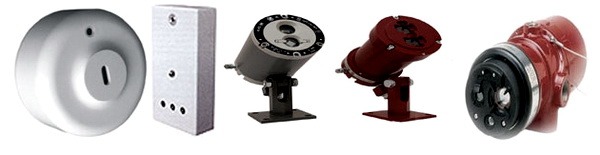
A highly sensitive photocell detects the appearance of a spectrum of optical flame waves. The fire sensor design is complex, so the sensor is expensive. In this regard, they are rarely used in residential buildings, but they have become popular in gas and oil production enterprises.
Simple flame sensors can be triggered by welding work, bright sunlight, some types of lamps. To prevent false alarms, special light filters are used.
Non-addressable (traditional) fire alarm system
In such systems, control panels determine the state of the alarm loop by measuring electricity in an alarm loop with detectors installed in it, which can only be in two static states: “normal” and “fire”. When a fire factor is detected, the detector generates a “fire” notification, abruptly changing its internal resistance and, as a result, the current in the alarm loop changes. It is important to separate alarm notifications from service notifications associated with faults in the alarm loop or false alarms. Therefore, the entire range of loop resistance values for the control panel is divided into several areas, each of which is assigned one of the modes (“Normal”, “Attention”, “Fire”, “Fault”). Detectors are connected to the alarm loop line in a certain way, taking into account their individual internal resistance in the “normal” and “fire” states. For traditional systems, such features are provided as the ability to automatically reset the fire detector power supply in order to confirm the activation, the ability to detect several triggered detectors in a loop, as well as the implementation of mechanisms to minimize the influence of transient processes in the loops.Addressable threshold fire alarm system
The difference between an addressable threshold signaling system and a traditional one lies in the topology of the circuit design and the algorithm for polling sensors. The control panel cyclically polls connected fire detectors to find out their status. Moreover, each detector in the loop has its own unique address and can already be in several static states: “normal”, “fire”, “fault”, “attention”, “dusty”, etc. Unlike traditional systems, such a polling algorithm allows you to determine the location of a fire with accuracy down to the detector. Fire safety standards in Russia allow the installation of one addressable detector to detect a fire, provided that when this fire detector is triggered, a signal is not generated to control fire extinguishing installations or type 5 fire warning systems.Addressable analogue fire alarm system
Addressable analogue systems are currently the most progressive; they have all the advantages of addressable threshold systems, as well as additional functionality. In analogue addressable systems, the decision about the state of the object is made by the control device, not the detector. That is, in the configuration of the control device, response thresholds are set for each connected addressable device (“Normal”, “Attention” and “Fire”). This allows you to flexibly create fire alarm operating modes for rooms with varying degrees of external interference (dust, level of industrial smoke, etc.), including during the day. The control device constantly polls connected devices and analyzes the received values, comparing them with the threshold values set in its configuration. In this case, the topology of the address line to which the detectors are connected can be circular. In this case, a break in the address line will lead to the fact that it will simply split into two radial independent loops, which will fully retain their functionality. The listed features of addressable analogue systems provide such advantages over other types of fire alarm systems as early detection of fires and a low level of false alarms. Monitoring the performance of fire detectors in real time allows you to identify detectors that are promising for maintenance in advance and draw up a plan for specialist visits service organization to the object. The number of protected premises by one controller is determined by the addressable capacity of this controller.About the applicability of systems
At first glance, it is advisable to use traditional systems at small and medium-sized facilities, when one of the main selection criteria is the relatively low cost of the system. And the cost of the system is largely determined by the cost of the detector. Today, conventional non-addressable detectors are relatively cheap. Despite the fact that the use of modern digital signal processing algorithms in control and control devices can significantly increase the reliability of signal detection from detectors, and as a result, reduce the likelihood of false alarms, it is still necessary to take into account that often such detectors do not provide a sufficient level of reliability. And - as a consequence of this fact - the need to install at least two or even three detectors in one room. Traditional systems do not provide ease of installation - the loops in such systems can only be radial. Accordingly, the larger the system, the more communication lines need to be installed and the more detectors to install. When the reliability criterion comes to the fore, we can already talk about installing an addressable threshold or addressable analogue system at the site. At the same small and medium-sized facilities, it is advisable to use addressable threshold systems that combine the advantages of addressable analog and traditional systems. IN in this case We can already install one detector in a room (the cost of which is slightly lower than the cost of an addressable analog detector), a free line topology (bus or ring), and for addressable detectors there is no need to use VUOS. However, it is worth considering that for such systems it is not possible to use short-circuit insulators in the loop, and also to determine the exact location of breaks in the ring loop. Maintenance of such systems is also carried out in a preventative manner. Analogue addressable systems do not have such disadvantages. The advantages of installing such systems are obvious - a free topology plus the ability to use short-circuit insulators and determine the location of a line break, the ability to set analog values for alarm messages "Attention", "Fire" (and these values may be different for day and night), as well as for value of "Dust content". When using an addressable analogue system, savings on maintenance are obvious - monitoring the performance of fire detectors in real time allows you to identify detectors that are promising for maintenance in advance and draw up a plan for specialists from a service organization to visit the site. In the software of addressable analogue microcontrollers detectors from the Bolid company have implemented algorithms that eliminate false alarms under various environmental influencesNon-addressable fire alarm system using ISO Orion devices
To build a non-addressed fire alarm system in the Orion integrated security system manufactured by the Bolid company, you can use the following control panels with monitoring of radial alarm loops: All devices, with the exception of Signal-20P, can operate in autonomous mode. However, when using devices to organize fire alarms, the system usually also uses a network controller - the “S2000M” (or “S2000”) remote control. The console in PS systems can perform functions of displaying events occurring in the system, as well as relay control functions if additional relay modules are used. If display units are required, a remote control is also required. Depending on the type of connected fire detectors, when programming device configurations, the loops can be assigned one of the types:Type 1. Fire smoke with double trigger recognition.
Fire smoke detectors (normally open) are included in the AL. Possible modes (states) of AL:- “Open” – loop resistance is more than 6 kOhm;
Type 2. Firefighter combined single-threshold.
The alarm system includes fire smoke (normally open) and heat (normally closed) detectors. Possible modes (states) of AL:- “On guard” (“Armed”) – the alarm system is controlled, the resistance is normal;
- “Disarmed” (“Disarmed”) – the alarm system is not controlled;
- “Attention” – a heat detector has been triggered or a smoke detector has been triggered again;
- “Fire” - expired after the detector was triggered “Transition delay to Alarm/Fire”;
- “Short circuit” – loop resistance is less than 100 Ohms;
- “Open” - loop resistance is more than 16 kOhm (more than 50 kOhm for “S2000-4”);
- “Failure to arm” - the alarm system was violated at the moment of arming.
Type 3. Fireman's thermal two-threshold.
Fire thermal (normally closed) detectors are included in the AL. Possible modes (states) of AL:- “On guard” (“Armed”) – the alarm system is controlled, the resistance is normal;
- “Disarmed” (“Disarmed”) – the alarm system is not controlled;
- “Arming delay” – the arming delay has not ended;
- “Attention” – the activation of one detector is recorded;
- “Fire” - the activation of more than one detector is recorded, or after the activation of one detector the “Transition delay to Alarm/Fire”;
- “Short circuit” – loop resistance less than 2 kOhm;
- “Open” - loop resistance is more than 25 kOhm (more than 50 kOhm for “S2000-4”);
- “Failure to arm” - the alarm system was violated at the moment of arming.
- Delay of transition to Alarm/Fire - for any of the fire loops this is the time of transition from the “Attention” state to the “Fire” state. Loops of type 1 and type 3 (with double trigger recognition) can also go into the “Fire” state when the second fire detector in the alarm loop is triggered. If the “Delay for transition to Alarm/Fire” is 255 s, then the device does not switch to the “Fire” mode in time (infinite delay). In this case, loop types 1 and 3 can go into the "Fire" state only when the second detector in the loop is triggered, and loop type 2 will not go into the "Fire" state under any circumstances.
- AL analysis delay after power reset is the duration of the pause before loop analysis after removing the loop supply voltage (when re-querying the state of the fire loop and when arming). This delay allows detectors with a long readiness time (calm-down time) to be included in the loop.
- Without the right to disarm – does not allow the loop to be disarmed under any conditions.
- Auto arming from Alarm/Fire – the loop will automatically switch to the “Armed” state as soon as the loop resistance is normal for a time equal to the numerical value of this parameter multiplied by 15 s.
- Enable/disable if at least one of the loops associated with the relay has entered the “Fire” state;
- Turn on/off temporarily if at least one of the loops connected to the relay has entered the “Fire” state;
- Flash from the on/off state if at least one of the loops associated with the relay has switched to the “Fire” state;
- “Lamp” – blink if at least one of the loops connected to the relay has switched to the “Fire” state (blink with a different duty cycle if at least one of the connected loops has switched to the “Attention” state); turn on if the associated loop(s) are taken, turn off if the associated loop(s) are removed. In this case, anxiety states are given higher priority.
- “Central monitoring station” - turn on when at least one of the loops connected to the relay is taken, in all other cases - turn off;
- “ASPT” - Turn on for a specified time if two or more loops associated with the relay have entered the “Fire” state and there is no violation of the technological loop. A broken technological loop blocks switching on. If the technological loop was violated during the relay control delay, then when it is restored, the output will be turned on for the specified time (violation of the technological loop suspends the counting of the relay activation delay
- “Siren” - If at least one of the loops connected to the relay has switched to the “Fire” state, switch for a specified time with one duty cycle, if in the attention state - with another;
- “Fire monitoring station” - if at least one of the loops associated with the relay has entered the “Fire” or “Attention” state, then turn it on, otherwise turn it off;
- “Fault” output - if one of the loops associated with the relay is in the “Fault”, “Failure to Arm”, “Disarmed” or “Arm Delay” state, then turn it off, otherwise turn it on;
- Fire lamp - If at least one of the loops associated with the relay has switched to the “Fire” state, then blink with one duty cycle, if in “Attention”, then blink with another duty cycle, if all the loops associated with the relay are in the “Armed” state, then turn on, otherwise turn off;
- “Old monitoring station tactics” - turn on if all the loops associated with the relay are taken or removed (there is no “Fire”, “Fault”, “Failure” condition), otherwise turn off;
- Turn on/off for a specified time before taking the loop(s) associated with the relay;
- Turn on/off for a specified time when picking up a loop(s) associated with a relay;
- Turn on/off for a specified time when the loop(s) associated with the relay are not removed;
- Turn on/off when removing the loop(s) associated with the relay;
- Turn on/off when taking the loop(s) associated with the relay;
- “ASPT-1” - Turn on for a specified time if one of the loops associated with the relay has entered the “FIRE” state and there are no broken process loops. If the process loop was violated during the relay control delay, then when it is restored, the output will be turned on for the specified time (violation of the process loop suspends the counting of the relay activation delay);
- “ASPT-A” - Turn on for a specified time, if two or more loops connected to the relay block the turn on, when it is restored, the output will remain off;
- “ASPT-A1” - Turn on for a specified time if at least one of the loops associated with the relay has switched to the “FIRE” state and there are no broken process loops. A damaged process loop blocks switching on; when it is restored, the output will remain switched off.
ISO "Orion" control and monitoring devices in offline mode
PPKOP S2000-4
"S2000-4" is used in autonomous mode at small facilities. For example, the device can be used in small shops, small offices, apartments, etc. The device has:- Four alarm loops, which can include any type of non-addressable fire detectors. All loops are freely programmable, i.e. for any loop, you can set types 1, 2, 3, and also configure other configuration parameters individually for each loop.
- Two relay outputs of the “dry contact” type and two outputs with monitoring of the health of connection circuits. You can connect actuators (light and sound alarms) to the relay outputs of the device, and also transmit notifications to the monitoring station using a relay. In the second case, the relay output of the object device is included in the so-called “general alarm” loop of the notification transmission device, which has a built-in transmitter via the GSM channel and/or an output for connection to the GTS. Thus, when the device switches to the “Fire” mode, the relay closes, the general alarm loop is broken and an alarm notification is transmitted to the monitoring station via GSM channels or via the telephone network;
- Circuit for connecting a reader (you can connect various readers operating via the Touch Memory, Wiegand, Aba Track II interface).
Control Panel Signal-10
"Signal-10" is used in autonomous mode at small and medium-sized facilities. The device has a convenient function for controlling the state of zones using contactless identifiers - Touch Memory or Wiegand keys (up to 85 user passwords). The powers of each key can be flexibly configured - to allow full control of one or an arbitrary group of loops, or to allow only the transfer of loops. The powers of each key can be flexibly configured - to allow full control of one or an arbitrary group of loops, or to allow only the transfer of loops. The device has:- Ten alarm loops, which can include any type of non-addressable fire detectors. All loops are freely programmable, i.e. for any loop you can set types 1, 2 and 3, and also configure other configuration parameters individually for each loop.
- Two relay outputs of the “dry contact” type and two outputs with monitoring of the health of connection circuits. You can connect actuators (light and sound alarms) to the relay outputs of the device, and also transmit notifications to the monitoring station using a relay. In the second case, the relay output of the object device is included in the so-called “general alarm” loop of the notification transmission device, which has a built-in transmitter via the GSM channel and/or an output for connection to the GTS. Thus, when the device switches to the “Fire” mode, the relay closes, the general alarm loop is broken and an alarm notification is transmitted to the monitoring station via GSM channels or via the telephone network.
- Circuit for connecting the reader, which is used to implement convenient way control arming and disarming using electronic keys or cards. You can connect any Touch Memory key readers or contactless Proxy cards that have a Touch Memory interface at the output (for example, “Reader-2”, “S2000-Proxy”, “Proxy-2A”, “Proxy-3A”, etc. ).
- Ten alarm loop status indicators and a functional indicator of the device operation.
Control Panel Signal-20M
"Signal-20M" can be used at small and medium-sized objects (for example, warehouses, small offices, residential buildings, etc.). To control the state of zones, PIN codes can be used (64 user PIN codes are supported). User permissions (for each PIN code) can be flexibly configured - to allow full control, or to allow only re-arming. Any user can manage an arbitrary number of loops; for each loop, arming and disarming powers can also be individually configured. Twenty alarm loops of "Signal-20m" provide sufficient localization of the alarm notification at the mentioned objects when any security detector in the train. The device has:- Twenty alarm loops, which can include any types of non-addressable fire detectors. All loops are freely programmable, i.e. for any loop you can set types 1, 2 and 3, and also configure other configuration parameters individually for each loop;
- Three relay outputs of the “dry contact” type and two outputs with monitoring of the health of connection circuits. You can connect actuators (light and sound alarms) to the relay outputs of the device, and also transmit notifications to the monitoring station using a relay. In the second case, the relay object output of the device is included in the so-called “general alarm” loop of the notification transmission device, which has a built-in transmitter via the GSM channel and/or an output for connecting to the GTS. The operating tactics for the relay are determined, for example, turn on during an alarm. Thus, when the device switches to the “Fire” mode, the relay closes, the general alarm loop is broken and an alarm notification is transmitted to the monitoring station via GSM channels or via the telephone network;
- Keyboard for controlling the state of zones on the device body using PIN codes. The device supports up to 64 user passwords, 1 operator password, 1 administrator password. Users can have rights either to arm and disarm alarm loops, or only to arm, or only to remove. Using the operator password, it is possible to put the device into test mode, and using the administrator password, enter new user passwords and change or delete old ones.
- Twenty alarm loop status indicators, five output status indicators and functional indicators “Operation”, “Fire”, “Fault”, “Alarm”.
Non-addressed fire alarm system in ISO ORION
Figure 4 shows an example of organizing a non-addressed fire alarm system using ISO Orion devices. It is possible to connect threshold fire detectors of various types (smoke, heat, flame, manual) to each of the devices. The alarm loops of each device are freely programmable, i.e. for any loop, you can set types 1, 2 and 3, and also configure other configuration parameters individually for each loop. Each device has relay outputs, with which you can control various actuators - light and sound alarms, as well as transmit an alarm signal to the central monitoring console. For the same purposes, you can use the S2000-KPB control and launch unit. Additionally, the system is equipped with a “S2000-BI” display unit, which is designed to display the status of instrument zones at the observation post. Control of the state of zones, as well as viewing of system events, is carried out from the network controller - the “S2000-M” remote control. Often the remote control is also used to expand the fire alarm system - to connect additional control panels or relay modules. That is, to increase the performance of the system and its expansion. Moreover, the expansion of the system occurs without its structural changes, but only by adding new devices to it.Addressable threshold fire alarm system using ISO Orion devices
To build an address-threshold fire alarm system in ISO "Orion" the following are used:- Reception and control device "Signal-10" with address-threshold mode of alarm loops
- Smoke optical-electronic threshold-addressable detector "DIP-34PA"
- Thermal maximum-differential threshold-addressable detector "S2000-IP-PA"
- Manual threshold-addressable detector “IPR 513-3PA”
- “Fire” - at least one addressable zone is in the “Manual fire” state, two or more addressable zones are in the “Fire” state, or the alarm/fire delay has expired;
- “Attention” - at least one address zone is in the “Fire” state;
- “Fault” - one of the addressable zones is in the “Fault” state;
- “Disabled” - one of the address zones is in the “Disabled” state;
- “Non-arming” - at the moment of arming, the addressable zone is in a state different from the “Normal” state;
- “Dusty, maintenance required” - one of the address zones is in the “Dusty” state;
- “Disarmed” (“Disarmed”) – one of the address zones is disarmed;
- “On guard” (“Armed”) – all addressable zones are normal and armed.
Addressable analogue fire alarm system using ISO Orion devices
Addressable analogue fire alarm system in ISO "Orion" is built using the following devices:- Controller of two-wire communication line “S2000-KDL”;
- Fire smoke optical-electronic addressable analogue detector “DIP-34A”;
- Firefighter thermal maximum differential addressable analog "S2000-IP"
- Fire manual addressable call point "IPR 513-3A"
- Branching and insulating blocks "BREEZ", "BREEZ" used. 01. The devices are designed to isolate short-circuited areas with subsequent automatic recovery after the short circuit is removed. "BREEZE" is installed in the line as a separate device, "BREEZE" is used. 01 is built into the base of fire detectors “S2000-IP” and “DIP-34A”
- Address expanders “S2000-AR1”, “S2000-AR2”, “S2000-AR8”. The devices are designed for connecting non-addressable four-wire detectors. Thus, conventional threshold detectors can be connected to the addressable system.
- “Taken” – the zone is completely controlled;
- “Disabled” – the zone is normal if there are no faults;
- “Failure to arm” – the controlled parameter of the control system was not normal at the time of arming;
- “Arming delay” – the zone is in the arming delay state;
- “Fire” – the addressable heat detector has detected a change or excess of the temperature value corresponding to the condition for switching to the “Fire” mode (maximum differential mode); address manual call point transferred to the "Fire" state (glass breaking). For addressable expander loops, there are certain loop resistance values corresponding to this state;
- “Short circuit” – For addressable expander loops, there are certain loop resistance values corresponding to this condition;
- “Fire equipment malfunction” – the measuring channel of the addressable heat detector is faulty.
- “Taken” – the zone is controlled, the thresholds “Fire”, “Attention” and “Dusty” are not exceeded;
- “Removed” – only the “Dusty” threshold and faults are monitored;
- “Fire equipment malfunction” – the measuring channel of the addressable detector is faulty;
- “Service required” – the internal threshold for automatic compensation of dust content in the smoke chamber of the addressable detector or the “Dusty” threshold has been exceeded.
- “Taken” – the zone is controlled, the “Fire” and “Attention” thresholds are not exceeded;
- “Cleared” – only faults are monitored;
- “Arming delay” – the zone is in the arming delay state;
- “Failure to arm” – at the time of arming, one of the “Fire”, “Attention” or “Dusty” thresholds has been exceeded or a malfunction is present;
- “Attention” – the “Attention” threshold has been exceeded;
- “Fire” – the “Fire” threshold has been exceeded;
- “Fire equipment malfunction” – the measuring channel of the addressable detector is faulty.
- Automatic re-arming from alarm - allows automatic transition from the “Alarm”, “Fire” and “Attention” states to the “Armed” state when the zone violation is restored. In this case, in order to transition to the “Armed” state, the zone must be normal for a time no less than that specified by the “Recovery time” parameter.
- Without the right to disarm – serves to allow the zone to be constantly monitored, that is, a zone with this parameter cannot be disarmed under any circumstances.
Explosion-proof solutions based on addressable analogue fire alarm system
If it is necessary to equip a fire alarm for an object with explosive zones, together with an addressable analogue system built on the basis of the S2000-KDL controller, it is possible to use intrinsically safe barriers "BRShS-ex" (Figure 7). This unit provides protection at the level of an intrinsically safe electrical circuit. This method of protection is based on the principle of limiting the maximum energy accumulated or released by an electrical circuit in emergency mode, or dissipating power to a level significantly below the minimum energy or ignition temperature. That is, the voltage and current values that can enter the danger zone in the event of a malfunction are limited. The intrinsic safety of the unit is ensured by galvanic isolation and the appropriate selection of the values of electrical clearances and creepage paths between intrinsically safe and associated intrinsically hazardous circuits, limiting voltage and current to intrinsically safe values in the output circuits through the use of compound-filled spark protection barriers on zener diodes and current-limiting devices, ensuring electrical clearances, leakage paths and integrity of spark protection elements, including due to their sealing (filling) with a compound. BRShS provides:- receiving notifications from connected detectors via two intrinsically safe loops by monitoring their resistance values;
- power supply to external devices from two built-in intrinsically safe power supplies;
- relaying alarm messages to the two-wire communication line controller.
- Foton-18 – security passive optical-electronic detector;
- Foton-Sh-Ex – security infrared passive optical-electronic “curtain” detector;
- Steklo-Ex – security acoustic detector;
- Shorokh-Ex – security surface vibration detector;
- MK-Ex – security magnetic contact detector;
- STZ-Ex – flood alarm;
- IPD-Ex – optical-electronic smoke detector;
- IPDL-Ex - optical-electronic linear smoke detector;
- IPP-Ex – infrared flame detector;
- IPR-Ex - manual call point
Additional capabilities of the PS when using the software
In some cases, when constructing a fire alarm system, it is used Personal Computer with a specialized software. The software can expand the functionality of the S2000M remote control, namely, it can be used to organize an automated workstation of the control post, keep a log of events and alarms, indicate the causes of alarms, collect statistics on addressable fire detectors, as well as build various reports. To organize automated workstations in ISO "Orion", the following software can be used: AWP "S2000", AWP "Orion PRO". AWP "S2000" allows you to implement the simplest functionality - monitoring system events. This software can be used if it is necessary to monitor several autonomous devices from an observation post and log events. In this case, the fire alarm is controlled directly from the control elements of the devices (“Signal-20M”) or from the readers (“S2000-4”, “Signal-10”). PCs with Orion PRO workstation allow you to implement the following functions:- Accumulation of OS events in the database (based on PS alarms, operator reactions to these alarms, etc.);
- Creating a database for a protected object - adding loops, sections, relays to it, arranging them on floor plans;
- Creating access rights to manage PS objects (loops, sections), assigning them to duty operators;
- Placement of logical substation objects (loops, partition areas, relays) on graphic floor plans of premises
- Interrogation and control of control and control devices connected to a PC, including remote controls. That is, from a computer you can simultaneously interrogate and control several subsystems, each of which operates under the control of a remote control;
- Setting up automatic system reactions to various events;
- Displaying the state of the protected object on graphic plans of premises, managing logical PS objects (loops, sections);
- Registration and processing of fire alarms occurring in the system, indicating the reasons, service marks, as well as their archiving;
- Providing information about the state of PS objects in the form of an object card;
- Generating and issuing reports on various PS events;
- Displays CCTV cameras, as well as manages the status of these cameras.
Given the huge number of types and modifications of alarm devices and devices, it is impossible to know them all, and it is not necessary. It is enough to understand the basic principles of the construction and operation of alarm systems and be able to work with technical documentation for devices.
The alarm system in its various modifications (security, fire, automobile) is essentially the same. Figure 1 shows the general block diagram of signaling, where:
- D - alarm sensor
- UOS - signal processing device
- IU - actuator
- LS - communication line
- UTD - data transmission device
- UA - warning device
- IP - power supply
An alarm sensor (for security alarms the term “detector” is used) is a device that, under a certain influence on it, changes the characteristics of the electrical circuit in which it is connected. Depending on their purpose, sensors can respond to temperature changes, sound vibrations, vibrations, etc.
A relay is most often used as an output device in detectors, which closes or opens an electrical circuit (alarm loop) or changes its current consumption. However, there are sensors that generate a digital signal. Various types Alarm sensors, installation diagram, connection of detectors are discussed in more detail in the sections “Security Equipment, Fire Alarm DEVICES”, “INSTALLATION OF SECURITY FIRE ALARM”.
The signal processing device (receiving and control device) monitors changes in the state of the detectors and, with the help of actuators (usually relays), turns on warning devices (sirens, warning lights). If it is necessary to transmit notifications about the status of the alarm system to remote distances, for example to a security console, a data transmission device is used. The above sections also contain additional information about this equipment.
A power source is naturally needed for all devices. The design of the devices may include built-in power supplies; some types of detectors are powered via an alarm loop.
 As already noted, the given signaling diagram is a generalized version; some of its elements may be missing in specific systems.
It is worth noting that such abstractly theorized schemes are not always easy to understand, so I will give a signaling scheme that is simple to the point of primitiveness, which, however, contains most of the devices discussed above, uses general principles construction and operation of security alarm systems (Fig. 2.1 corresponds to the “security” mode, Fig. 2.2 - “alarm”).
The role of the sensor is performed by wire 1, laid covertly along the protected perimeter and having a low breaking force. The current I1 flowing through it from battery 4 triggers relay 2 (analogous to a control panel), which keeps its contacts (actuator) in the open state.
If the wire breaks, the relay is de-energized and switches the contacts to a closed state, supplying power to bell 3 (announcement device), which generates an “alarm” signal.
I would like to note that most alarm systems work exactly according to this principle, using, of course, more complex circuit solutions. In addition, automation systems work similarly. For example, use a water detection sensor, connect an electromechanical valve or gate valve to the actuator, and you will receive an emergency water supply shutdown system when leaks are detected.
© 2010-2020. All rights reserved.
The materials presented on the site are for informational purposes only and cannot be used as guidance documents.