We are often asked about wiring pickups on different guitars and we have come to the conclusion that many guitarists do not understand how it works and what the difference in sound is. Few people know what serial and parallel wiring of pickups is, what phase switching and coil cutting are. We decided to put things in order by dotting all the “e”s.
Wiring of pickups in a standard Stratocaster
Understanding the very concept of series and parallel circuits can seriously expand your sound range, you will understand how to solder pickups, how to resolder guitar cabinets to a different ohm resistance, and you will also understand how the effects loop in your amplifier works, so you can tune the sound that you want. which you need. Is not complex issue, but it can be difficult to find direct answers to your questions on the Internet. Let's start with the most popular method of wiring pickups on electric guitars with two or three pickups - parallel wiring.
Think of the parallel circuit as railroad tracks. Each of the rails is independent of each other, just like + and - in an electronic circuit. Plus the earth is sleepers. The output from the pickup is connected to the pickup switch, and the ground is connected to one point (usually back side volume potentiometer). To better understand how this works, take a look at the diagram above.

Sensor wiring by Brian May (Queen)
Brian has three single-coil pickups in series, so his guitar doesn't sound like a Strat. Notice how the current flows through the sensors. Even with the many phase switches on Brian May's guitar, the output of one pickup is connected to the input of another. This is how you connect your effects pedals together. These two methods of wiring pickups give us two various types sound, both of them are quite applicable. No only the right way pickup connections and many guitarists prefer to have both options for maximum versatility. Okay, let's leave the associations and move on to the most interesting thing - the difference in sound. Imagine how a Strat sounds in second position (neck/mid) or fourth position (mid/bridge). Do you hear the classic ringing sound Strat with low noise level and small output (song Sultans of Swing - good example). The two sensors work as a kind of filter, lowering each other's resistance. This is the essence of parallel wiring and it is what gives you that pure sound - ringing, glassy, elastic and sparkling. This is why Brian May's guitar has nothing in common with a Strat; rather, its pickups sound similar to humbuckers. Pause and listen to the following two examples of guitar sounds with different types pickup wiring. The first example is a Telecaster with a 4-way switch, the second is a Strat with the S-1 system.
A humbucker is a pickup with two reverse-polarity, reverse-wound coils connected in series. Humbuckers sound darker (as in the examples above) + they have more powerful output. However, 4-wire humbuckers can be connected in parallel and produce a single-coil sound that is bright and ringing. Seymour Duncan writes on their website that “a humbucker connected in parallel is 30% quieter than one connected in series.”

A humbucker is a pickup with two coils of reverse polarity and windings.
When connected this way, the pickup will sound similar to 2 single coils placed side by side due to its reverse polarity and winding. Although we don't have an audio example for you, you may be able to find what you need on YouTube, just search for “series parallel humbucker.” I hope we've cleared things up a little bit about why single coils and humbuckers sound different. In addition to the materials from which they are made, different connections of sensors give almost the exact opposite result. Good luck experimenting with your sound!
In the last article, we looked at the general wiring of a humbucker and learned how to solder it according to the circuit of one tone + volume knob + tone knob. Now it’s time to complicate the task a little and add a neck humbucker to the bridge humbucker we already have. Well, it’s natural to switch between them using a three-position switch.
We will create three operating modes:
- bridge humbucker;
- both sensors;
- neck humbucker.
In general, the scheme is very popular nowadays. And I think the information in this article will definitely be useful to you. Let's start with the option with one volume knob for both sounds.
Three position switch
Let's look at the operation of a three-position switch. In guitars they come in two types:
- slider type;
- blade type.
Used primarily in Strat-like guitars. Has 2 pairs of contacts of 4 pieces each. Each pair has its own separate switch. That's why it is called two-pole. To switch between sensors, follow the diagram presented in the figure:
We solder the middle and outer contacts to the volume knob, and connect the wires from the pickups to the switch inputs, as in the figure. Thus, when turning the switch knob to the middle position, both middle contacts will close, only the bridge contact will close to the left position, and only the neck contact will close to the right position.
This type of switch is found on Gibson Les Paul guitars. Schematically, the switch can be represented as follows:
From the picture you can see that the entire switch can be represented as 2 paired on-off switches. In position 1, only contact A is closed, in position 2 both contacts are closed, and in position 3 only contact B is closed. Thus, in the left position the neck sensor will work, in the middle - both, and in the right the bridge sensor. To obtain the required neck bridge positions, simply solder the outputs from the sensors to the required switch pins A and B, and solder pins 1 and 2 to the output jack or to the volume knobs, depending on the version of your circuit.
Wiring diagram for two humbuckers
Below is a diagram of the soldering of pickups with a three-position slide switch, one volume and tone knob. The operating principle is as follows: we immediately send the signal from each sensor to the switch input. Next, from its output we feed the signal to the volume knob through the tone knob. From the volume the signal goes to the jack.
 |
Now consider a circuit with two volumes and one common tone. This time we use a lever switch. The operating principle is as follows: we first send the signal from each sensor to its own volume knobs. Next, we connect the output from the volume potentiometers to the switch inputs. Well, we pass the outputs from it through the tone knob and send it to the jack.
 |
And here are 2 more popular options for desoldering sounds we looked at in this article. Once again, I repeat that these are just connection options, demonstrating which I wanted to show the principle of wiring pickups. It all depends on your needs, you have the right to make adjustments.
Last time I described different variants obtaining a different sound using pickups. This time I will describe the modifications of the tone block.
Potentiometers
What is a potentiometer? This is a variable resistor. The electronics are designed in such a way that when we turn down the volume, part of the signal goes to ground, and the rest goes to the amplifier. The origin of the potentiometer does not affect the sound, but their parameters do. And by changing the values of the potentiometers, you can achieve a different sound.
Potentiometers aren't perfect either. And even when they are turned to maximum, part of the signal still goes to ground, which causes losses in power and high frequencies. The losses are not very large, but nevertheless audible. Therefore, the greater the resistance of the potentiometer, the less loss. Potentiometers with a nominal value of 250 kOhms are usually installed on single-coils, and 500 kOhms on humbuckers, since humbuckers sound muddier and the high frequencies there are initially lower than those of single-coils. A brighter sound will be obtained when using 1 MΩ potentiometers.
Keeping the top
However, increasing the potentiometer value does not solve the problem of loss of highs when the guitar's volume is reduced. And the solution to the problem is quite cheap and simple, and is sold in any radio parts store. It is enough just to insert a 0.001 uF capacitor onto two contacts of the volume potentiometer and all the high frequencies will remain in their original form. There is one caveat here - for normal implementation, a logarithmic potentiometer is required. With linear, the volume change will be sharp and stepped. By the way, this is what makes old Fender Telecasters so ringing at any volume level.
Going to the depths
From the previous it is clear that the capacitor conducts high frequencies. Actually, the tone control is a capacitor and a resistor. Typically, guitars are equipped with capacitors with a nominal value of 0.022 or 0.047 uF, but in principle any can be installed. The higher the capacitor value, the more high frequencies will leak into the “ground” and the muddier the sound will be. Although, it doesn’t make sense to set more than 0.1 uF, but you can try.
One of the most interesting devices, which was used on some semi-hollow Gibson ESs, including the B.B. King Lucille and some Blueshawks. Unfortunately, I did not find a single accurate description of the design of this thing, since there is a lot of all kinds of garbage on this topic on the Internet. Even more unfortunately, I haven't been able to play a single guitar with this thing. However, from all sorts of descriptions and videos it is clear that Varitone “cuts off” certain frequencies from the signal. Consists of a position switch and capacitors. First things first.
A simple variton, as it is depicted on the Internet, is an ordinary bunch of capacitors soldered to a positioner. When a position is selected, the signal is sent to a specific capacitor and then to the tone potentiometer. In fact, this gives you the opportunity to choose which capacitor to play through and how deep the timbre will be. A similar thing was implemented in Gretsch guitars in the form of a three-position toggle switch.

More interesting is the design of Gibson's original Varitone. It makes it possible to “cut out” frequencies, radically changing the sound. With such a thing, you don’t need anything else practically, no equalizer or cutoffs - all the sounds are already at your fingertips.

Killswitch
Regular switch. A simple two-position switch or button that turns off the signal completely. It can also be used in music - Buckethead uses this thing all the time.
Built-in booster
Instead of bothering with hot water bottles, why not build a booster into your guitar? There are battery-powered active boosters that will increase the guitar's output and pump up the amp.
Few people know that a booster can also be passive, and that you don’t need to spend a lot of money on it. To get real overload from the guitar itself, you just need to buy two diodes in the store. If they are connected correctly, they will give an overloaded signal, and if you also make adjustments, then no heaters are needed, and you can raise the output signal with one single switch.
It is even sold in stores, although not in ours. It's called Black Ice and consists of several diodes in one small package. By connecting them differently, you can achieve different sounds. But it is too expensive - buying regular diodes is much cheaper.

independence Day
Fans of turning on two pickups simultaneously on guitars with separate volume controls know that if you turn one volume to zero, the sound will disappear completely. However, the problem can be solved by simply rearranging the wires on the potentiometer, as in the diagram. After this, when turning the volume to zero, only a specific sensor will be turned off. Honestly, I don't know what the magic is, but it works.
True, there is also by-effect. The fact is that with such a connection, two sensors will always work, but at an extremely minimal volume - such that the second sensor will not even be heard.

Active electronics: equalizers, preamps, etc.
Nanotechnology allows you to build into the guitar any electronic crap that the user wants. The entire pedalboard can thus fit into the body of one guitar, but is it really necessary?
We looked at connecting one single-coil pickup directly. This time we'll delve deeper into the concept of guitar wiring.
Cut the sound!
Assuming we don't want to stop there, the simplest next step is to add " ". This is a simple switch that in one position leaves the sound as it is, and in another removes the sound completely. You might be thinking that we can just add a mini switch to the white wire ("signal") to cut the output from the stripper, like in the picture below:However, when we use this example of cutting off the "signal", we will get the same noise as if the cable was disconnected from the guitar. The two contacts in this case are not at equal voltages.
Instead, we must set the switch so that it still disables the stripper, but also completes the circuit:

This time in the "on" position of the switch, the "signal" wire is connected to the sensor output. In the "off" position it is connected directly to ground (while the output from the stripper is not connected to anything).
Now we have a "kill switch" that actually turns off the sound!
Turn up the volume
The “Kill switch” is certainly good, but the volume control is even more useful. The volume control uses a potentiometer that is hidden under the volume knob on the guitar. This is what it looks like:
As you can see, it has three contacts. The two outermost ones are connected by a resistive strip, and the middle one is connected to a contact that moves along the strip when the handle is turned. If we connect the "signal" to the left pin and the "ground" to the right pin, then by moving the middle pin we can control the output of the "signal" - full output, all the way to ground, or anywhere in between. By connecting this middle pin to the jack as in the picture below, we will connect a volume control to the circuit.

In this diagram you will notice that I have connected the ground wire in series on the right pin and on the back wall volume control. This way we ground the metal parts of the guitar. It so happens that the back of the potentiometer is used as a grounding conductor for all other wires that need grounding. There are pros, cons and exceptions, but discussing those is beyond the scope of this article.
Let's lower the tone
The last thing we were going to look at in this article was adding a tone knob. The tone control works differently than the volume control. It uses a potentiometer and capacitor together to desaturate the high frequencies in the signal to ground. By placing the RF capacitor on the “signal” we connect the high frequencies to “ground” using a potentiometer. That is, now, by rotating the potentiometer knob, we add RF to ground, thereby obtaining a decrease in their output.To connect the tone knob to the circuit, we connect the input of the volume pot (our "signal" from the pickup) to the tone pot at one end of the resistive strip. We then put a capacitor between the floating connection pin and ground (using the back of the potentiometer for ground). The other pin on the potentiometer is not used because we are using the potentiometer as a variable resistor and not as a voltage divider. Turning the knob toward zero allows more signal to reach the capacitor, where high frequencies are filtered and removed via ground. This is what it looks like:

That's all I was going to explain in this part. Now we have a guitar circuit with one pickup, volume and tone knobs. This is the circuit used in the prototype
Since our website contains a decent number of color schemes and wiring diagrams for various pickups, it would be quite logical to write a small manual that will help a person navigate the wires correctly. Some will simply find it useful, while others may start looking for options, fashions and various experiments. So, let's go.
Important!
This FAQ will only give a basic idea of the wiring options. Here they answer the question “How?”, not “Why?”. We strongly recommend that you carefully study as much information as possible, as well as look for examples of the sound that unusual wiring will produce, before you make it on your instrument.
Wiring diagrams can be viewed.
Pickup color schemes various brands— . The collection is updated and expanded.
If you want to understand the cutoff - .

You can also reverse the phase when connected in parallel. For those gentlemen who know a lot about perversions.
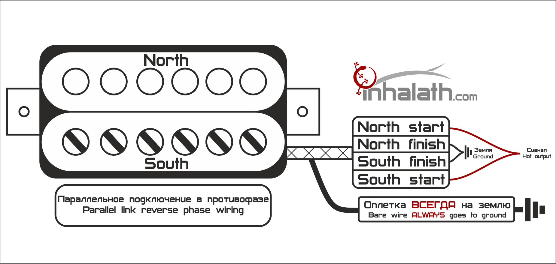
Note:
Phase/antiphase switching is also used in tone block mods through Push-Pull potentiometers and toggle switches. Although you can wire it to normal volume, although this is a dubious idea.
5. Conclusion.
These are all the options for connecting a humbucker. Some of them most likely will not be useful to you. The same Jimmy Page took his modified Les Paul to live performances, and there it helped him a lot, but when recording, you can achieve the desired sound with equalizers and post-processing. It should also be remembered that frequent re-soldering of the guitar can have a bad effect on the potentiometers, and extremely preferably remember standard connection humbucker.