!
The topic of soldering equipment occupies important part on YouTube channel Open Frime TV and continuing it, the author of the channel will assemble such a cordless soldering iron with unburnt tips.


The author has already assembled several cordless soldering irons, but they had copper tips, and constantly sharpening and cleaning the tip is still a problem, especially if you have to solder quite a lot, for example, at work. But, as they say, evolution does not stand still, and now the master presents to all lovers of homemade products an improved version of a cordless soldering iron with a so-called “eternal” tip. Such a tip does not need sharpening or cleaning. Unlike a copper tip, an “eternal” tip can be cleaned of carbon deposits very simply - with a damp cloth or sponge soaked in glycerin. No more files. I think this homemade product will be useful to many. The operating life on one charge is 30-40 minutes, this is quite enough for soldering most circuits, I think this operating time on one charge is quite reasonable. The soldering iron is equipped with an indicator LED that shows whether the soldering iron is currently turned on or not. Also, the soldering iron body has a built-in socket for charging a lithium-ion battery, in this case standard 18650, and of course this design is equipped with a switch. The dimensions turned out to be minimalistic, it is very convenient, I put it in my backpack and calmly carried it wherever I needed it.


Warm-up time is approximately 40-50 seconds. Let's first see what we need for assembly.
1) First of all for self-made we need a soldering iron like this lithium ion battery, and the larger the capacity, the better.

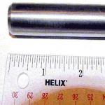
2) Next we also need a sting. It can be taken from any soldering station, you just need to make sure that the hole has a diameter of at least 4 mm.

3) We will also need a body. A 20 cc medical syringe copes with this task perfectly.

4) Well, then on to the little things: nichrome, glass tube and connecting wires. You will already see all this directly during assembly.

So let's start making it. Let's start preparing the body. We remove unnecessary elements from the syringe: the lower part and side ears.


We've sorted out the syringe, now let's make a holder for the sting. For this purpose we will use this extension tube.


It cannot be installed directly next to the housing; it may melt. Therefore, to attach it to the syringe, we will use a 4-millimeter textolite.

From it we will cut a “round” according to the diameter of the syringe, and the extension tube will be attached directly to this round.


It is also necessary to make holes for small screws for reliable fastening; if there is any play, the soldering process will begin to irritate.


When we have sorted out the fastening, we begin to make the heater. To make a heater we take nichrome wire. We unwind it by eye and connect it to the laboratory unit.

We set the voltage on it to 3.7 V. By changing the length of the nichrome, we achieve low heating of the spiral, approximately as in this picture:

Not too red, but the heating should be visible. Immediate answers to questions - where to get nichrome? There are quite a few such devices: these are old hair dryers, curling irons, kettles, in general, everything that once heated.

As you can see, at first the author wanted to use nichrome from a reel, but then he decided to take it from an old hair dryer to clearly demonstrate his words.
The heater needs to be wound on some kind of frame. The author decided to use copper wire. We put a glass tube on it a little longer than the length of the tip itself, screw the mounting wire to the nichrome and wind it evenly over the entire surface without shorting. When we have wound it, we put on another glass tube of a larger diameter to protect against short circuits on top and screw the second terminal.


Next, place the heating element in the tip. As you can see, he has difficulty getting inside. Great, no need to use additional sealant. After this, it is necessary to carry out a test switch on, you never know where there is a bad contact or something else.


It should be taken into account that the first switching on must be done in a well-ventilated area, since a lot of smoke is released when the glass tube warms up. The test was successful. You can also measure the current consumption, it should be around one and a half amperes.

Now let's put the parts of our soldering iron together. First, we connect the heater to the extension cord, then everything to the housing, and then the battery.


Now let's get into the electronics. The circuit diagram of the device is incredibly simple, but you need to draw it, since beginners are unlikely to understand it.


As you can see, there are no complex components or transistors or microcircuits here. So everything can be connected wall-mounted. The author uses a 3.5 mm plug as a charging socket.

This is because he has a standard charging board installed in the power supply, and as you may have noticed (if you have seen the previous videos of the author of the Open Frime TV channel) all the devices that he assembled are adapted for this charging. This solution is very convenient, there is no need to come up with a new one every time, it has already become like GOST for him.
To install electronics, you still need to make a couple of holes, namely for charging and an LED. And also close the top hole with another round piece of PCB. The switch will be attached to it.


When everything is ready, you can assemble it into one whole. This is very easy to do and anyone can do it.

After assembly, the author was not satisfied with the final appearance of the device, so to give it a marketable appearance, he decided to paint the case black.
This review examines a portable soldering iron that runs on batteries and is cordless. The device is fully functional, has its own niche, and can be used in practice. Next is a test.
A few words about “niche”. The device is intended for TROUBLESHOOTING AND MINOR REPAIRS. Not for installation (although you can also use it if there is nothing else). Why is this so - the soldering iron is much heavier than its wired brother and is inferior to it in power supply - it is simply inconvenient to swing it for a long time. On the other hand, it has no overlap with gas soldering irons - they are designed for “climbing onto the roof, soldering an antenna”; they are not suitable for picking electronics. The idea of such a soldering iron came to me while repairing a TV - Google told me about the treatment - 4 SMD transistors, one of which is rotten and needs to be replaced. Naturally, it turned out to be the last, and I had to do the following routine (since during the repair the box was just lying on the floor - I do not live in a workshop): Disconnect the TV from the network - disconnect the interfering cables - turn on the soldering iron and wait for it to heat up - replace the transistor - turn off soldering iron and take it away so as not to burn the carpet - the cables are in place - the box is in the network. And so 4 times :) If the soldering iron were small and cordless, it would simply lie on the TV chassis, and it would be its tail that would get in the way.
And so, I had to tighten it up 

Set: a protective cap-cover for the tip, a poor but working stand and a spiral of low-melting solder. When you put on the cover, the switch-on fuse moves and the soldering iron cannot be put into operation. 

I’m testing it: I’ve long wanted to replace the red LED in one of the mice with a blue one, the very job for this soldering iron. I swap LEDs along with ballast resistors 

Fine. It's quite possible to work. This is despite the fact that I use refractory solder 
it (according to the scale of a soldering iron with a thermostat) should be heated to 350 degrees, so that it does not have to be spread like plasticine. The soldering iron copes with non-massive terminals.
On the catcher and the beast - I was visiting, the light went out, I confiscated it, opened it - and it was already being repaired :) They changed the ballast. Soldered the flask like this 
As you can see, the near end has fallen off, and HOW it was soldered can be seen on the far end. Kick. I'm correcting 
The soldering iron tip warms up to operating temperature in about twenty seconds. Cooling to “can be removed” temperature - about a minute. For the long-playability test, I took an ancient power supply unit, which I should have thrown away a long time ago, but I was sorry for the parts. And everything there is massive. Well, I sat down and slowly soldered them. Of course, with a hundred-watt soldering iron and the appropriate tip, I would have split it apart in an instant, but, nevertheless, things went on 
In general, with eneloops inside, it really takes about half an hour of real work. (On the blister it says - 1 hour) During repairs, the entire TV can be plowed. Even Soviet. 
It looks like this in the hand 

Please note that in general the case hints that it should be held this way, it’s more convenient 
but then there is nothing to press the button with. The button is a blue, easy-to-press bubble located inside the orange safety slide. Until you move it, you can’t press the button. The activation of heating is indicated by the lighting of the red LED. Even a child can work - it’s easy 
Thick wires ( network cable, stranded) I was not able to solder it neatly with this solder. That is, everything is holding together, everything is strong, but there are lumps and snot due to lack of heating. In an emergency it will do, but then it will have to be redone.
Summary - with soldering of elements on printed circuit boards- it copes with a bang (the fallen wires from the diode on the star were also soldered normally, although it is more difficult than with a network solder), something large - there are already nuances.
The sting looks like this, it is easily removable 

Personally, on the farm, it “suited me.” I'm thinking of trying to convert it to lithium, or what?
Do you think the gadget is free? Well, no - a lot of points have accumulated, it’s time to shake them up a little...
Thank you for attention!
Sometimes there are situations when the owner simply cannot do without a simple soldering iron. For example, you need a multi-core cable for an outlet, or from a burnt-out appliance. At such moments, you have to either borrow a tool or postpone the matter indefinitely. After all, not everyone wants to buy an expensive soldering iron or soldering station, unless he is a repairman. However, there is a simple way out of this situation - to assemble a small soldering iron yourself, it is just suitable for small work. The manufacturing process will not take much time and effort, but you will be able to save some money and gain invaluable experience. Next, we will tell you how to make a soldering iron with your own hands at home. You will be offered several designs, and you can choose the one that suits you best.
Idea No. 1 – Use a resistor
First and most simple technology manufacturing electric soldering iron do it yourself - using a powerful resistor. The device will be designed to operate at voltages from 6 to 24 Volts, which will allow it to be powered from various current sources, and even make a portable version powered by a car battery. In order to make your own instrument, you will need the following materials:
To make your own soldering iron from a resistor at home, you must complete the following steps:
- You need to drill a hole in the end of a thick copper rod and drive the thread under the screw using a tap. It is also necessary to cut a groove for the retainer, which in our case is the spring ring. This can be done using a triangular file or a hacksaw for metal.

- From the second end, drill a hole with a diameter similar to that of a thin rod, which will act as the tip of a mini soldering iron.
- All elements of the rod must be assembled into one whole, as shown in the photo.

- The resistor is prepared for attaching the soldering iron tip, which must be inserted and secured at the back with a screw and washer.

- From a textolite or plywood plate you need to make a comfortable handle with your own hands with a seat for a resistor and wire. To do this, use a jigsaw to cut out two identical halves of the handle and make holes and recesses for screws and nuts.

- A power cord must be connected to the heater terminals. It must be screwed to ensure reliable contact.

- Ready homemade soldering iron twisted and checked.

We draw your attention to the fact that with such a portable gun you can easily solder microcircuits, even with your own hands. It can work not only from a power supply, but also from a battery. On the forums we came across many reviews where this option homemade products were connected from a 12 Volt cigarette lighter, this is also very convenient!
Please note that when first turned on, all soldering irons may smoke and stink for a while. This is normal for any model, as some elements burn out paint coating. This will stop later.
Video instructions for making a simple electrical appliance
Idea No. 2 – Second life for a ballpoint pen
There is another unusual one, but at the same time simple idea how to make a soldering iron with your own hands from scrap materials for soldering small parts or smd components. In this case, it will again be useful to us, but now not SEV (as in the previous version), but MLT, with a power of 0.5 to 2 Watts. 
So, first you must prepare the following materials:
- Ballpoint pen of the simplest design.
- Resistor with characteristics: resistance 10 Ohm, power 0.5 W.
- Double-sided textolite.
- Copper wire with a diameter of 1 mm, you can wind it from an old inductor or buy a single-core copper wire insulated at an electrical store and carefully remove it with a stationery knife
- Steel or copper wire with a diameter of no more than 0.8 mm.
- Wires for connecting to the network.
Making a soldering iron from a pen at home is quite simple, you just need to follow these steps:
- Remove the paint layer from the surface of the resistor. This operation can be carried out using sandpaper, a needle file or a file, or, in extreme cases, a knife. The main thing is not to overdo it, so as not to damage the resistor. If the paint is difficult to remove, connect the product to a regulated power source and heat it up a little.
- There are 2 wires coming out of the barrel, cut one of them and drill a hole in this place for the copper wire (diameter 1 mm). To prevent the wire from coming into contact with the cup (this must be avoided), make a countersink with a thicker drill, as shown in the photo below. In addition, you need to make a small cut for the wire directly on the resistor cup. A triangular file will help you with this again.

- Bend the steel wire into the shape of a handle with a fastening in the form of a ring, with a diameter similar to that of a drink on a cup. If you have copper wire, then you need to clamp the cup in it and twist it using pliers so that the contact is reliable, but do not overdo it, otherwise you will wrinkle the body. Remember that the wire must be without varnish insulation.

- Carefully cut out a board from a double-sided PCB with your own hands, exactly the same as shown in the example in the photo. It is not necessary to buy a new sheet of PCB. You can use a jigsaw to cut out a suitable piece from any unnecessary double-sided board. Or do without it altogether: twist the wire with wires and attach them to the handle using superglue. The main thing you need to pay attention to is that the distance between the heating element and the handle is more than 5 cm, otherwise the plastic may melt.

- Next, you need to assemble a homemade soldering iron from a handle, which should not cause any difficulties.

- All that remains is to install the thin tip into the seat. To prevent the copper wire from burning through the resistor, you need to make a protective layer of a piece of mica or ceramic between back wall and sting.

- The last thing you need to do is connect the homemade product to a 1 A power supply and a voltage of no more than 15 Volts using wires.

That's the whole technology for creating a homemade mini soldering iron at home. As you can see, there is nothing complicated in making this tool, and you can easily handle it, and all the materials can be found at home by disassembling old equipment or looking for them in bins.
How to make a more complex model of a mini soldering iron at home?
Video review of a device with nichrome wire operating on 12 Volts
Idea #3 – Powerful impulse model
This option is suitable for those who are already more or less familiar with radio engineering and know how to read the corresponding diagrams. A master class on making a homemade pulse soldering iron will be provided following the example of this diagram: 
The advantage of this tool is that the tip heats up within 5 seconds after turning on the power, and the heated rod can easily melt tin. At the same time, you can make it from a switching power supply from a fluorescent lamp, slightly improving the board at home.
As in previous examples, we will first consider the materials from which you can make a soldering iron with your own hands at home. Before assembly, you must prepare the following available tools:

All you need is to connect the tip to the secondary winding, which, in fact, is already part of it. After this, one of the ballast terminals must be connected to the primary winding of the transformer and all circuit elements must be secured in a reliable housing that will protect you from accidental damage electric shock, since the circuit contains a life-threatening voltage of 220 volts!
The principle of operation of this design is that the ballast from the lamp creates an alternating voltage, which is applied to the primary winding of the transformer and is reduced to low values, while the current increases many times. One turn, which is essentially the tip of the soldering iron, acts as a resistor through which heat is dissipated. When you press the button, current is supplied to the circuit, and rapid heating occurs; after the button is released, the tip quickly cools, which is very convenient, since you do not need to wait long for the instrument to heat up and cool down.


Idea No. 4 – Simple wire version
There is another option for making a miniature soldering iron - using nichrome wire. To do this you will need:

Manufacturing process:
- Drill a hole in the block for copper wire 3 times larger than its diameter.
- Place a piece of copper wire in it so that it protrudes about 5 cm and secure it there with thick plaster putty, let it dry.
- Place insulation on the copper rod, which is the tip, and wind required quantity nichrome wire, leaving a distance between the turns. Also put insulation on the ends and bring them closer to the handle. Then connect the twists with the wires. Tape them to the handle with electrical tape.

That's all, you have another simple and reliable design DIY soldering iron.
We still recommend using either the first or second option, which is more understandable and easier to manufacture. As for the transformer version, although it is more powerful, it is still not so convenient to use. We hope that these photo instructions were useful for you and finally, we recommend that you watch all the video examples in which the assembly process is discussed in more detail!
Also read:
Battery operated soldering iron – indispensable tool electrician, radio electronics engineer or electromechanician. However, what to do if there is no tool, but you urgently need to solder? The answer is simple. You need to make a battery-powered soldering iron with your own hands. In this case, it will not look like professional and commercial models, but will work no worse than one purchased from an electrical goods store.
A do-it-yourself soldering iron is in no way inferior in capabilities to store-bought counterparts.
What tools and materials will be needed to make such a soldering iron?
To make a soldering iron with your own hands at home or in a workshop (with a power of approximately 25-40 W to solder microcircuits, wires and other products), you must have:

Parts for assembling the soldering iron: body ballpoint pen, MLT resistor, copper, steel wire, double-sided textolite.
- newspaper;
- pliers;
- stationery knife with replaceable blades;
- stationery scissors;
- insulating tape;
- copper wire for the soldering iron tip;
- a small sheet of copper foil;
- iron tube (will be used as a case for the electric heater);
- heat-resistant plastic or wooden handle;
- any silicate glue or liquid glass;
- talc powder for electrical insulating mass;
- 2 AA batteries.
Making an electric soldering iron with your own hands is a fairly simple procedure that will not cause any difficulties or difficulties for many craftsmen.
The listed materials and tools can be easily found in any workshop, and if not available, purchased at the nearest electrical goods store.
If it was not possible to find a sheet of copper foil in the workshop, it can be replaced by foil-coated fiberglass - a material that is often found in printed circuits and circuit boards (the price of this component in electrical goods stores is approximately 200 rubles / sheet).
To separate the foil layer from the PCB, you must:
- heat the PCB sheet using an electric soldering iron or iron;
- screw the edge of the foil onto the body of a round pencil;
- As you move along the surface, wrap the foil around the round body of the pencil in the form of a tight tube.
When performing this operation, it is important to be extremely careful and evenly wind the foil to avoid damaging it.
Return to contents
Making the tip of the future soldering iron

To remove paint from a resistor, heat it using a power supply.
To make a soldering iron tip with your own hands, you need to take a thick piece of copper wire and sharpen one end to the required working angle ( this work It is better to do this on a table covered with newspaper, and use a regular stationery knife with replaceable blades and a small file as a working tool).
The sharpening angle of a standard tip can be shaped like a spatula or a screwdriver tip with a dihedral angle work surface with a bevel radius of 45 degrees. A standard tip can be made with a working surface thickness of 4-5 mm.
A miniature sting can be made with a thickness of 2-3 mm. A needle tip, sharpened to a needle-shaped cone, can have any tip thickness. A tip made for a specific type of work can have a shaped shape and any tip thickness.
Return to contents
How should the working surface of the soldering iron tip be processed?
The working surface of the soldering iron tip must be covered with a layer of solder, otherwise the uncovered part of the tip surface will burn. Burning of the non-working part of the tip is not critical, but the working part should always be in clean and perfect condition.
If the surface of the tip begins to fade during operation, it should be re-coated with a layer of solder. The finished tinned tip is used by the master as heating element soldering iron
Return to contents
Production of electrically insulating mass

The diameter of the resistor and the ring at the end of the wire must be the same.
To make an electrically insulating mass, mix silicate glue (liquid glass) and talc powder until the consistency of liquid sour cream. Apply the resulting mixture using a rigid inert plate or tweezers onto the cylindrical surface of the tip of the future soldering iron.
The mixture, obtained by mixing talcum powder and glue, has a very sticky consistency. Therefore, to prevent the instrument from sticking, it must be generously sprinkled with dry talc powder on top.
Return to contents
Making the base of a soldering iron heating element
To make the body of the heating element of a soldering iron, you should put a tube L = 30 mm, made of the thinnest copper foil, on the surface of the tip. This design will be used as the basis of the heating element of the soldering iron. The tip of the sting that comes out of the tube should not be longer than 10 mm.

For better contact Solder the ring to the resistor head.
The finished structure of the heating element of the soldering iron should then be coated thin layer electrically insulating mass and dry over a gas burner or electric stove at a working surface temperature of at least 150 degrees. The drying process should be continued until the layer of mass becomes hard (baked).
Next, screw a spiral winding onto the prepared heating element. To perform the procedure, you should use a thin (d=0.2 mm) nichrome wire approximately 350 mm long. Winding should be done in a spiral with extreme care, tightly winding the wire turn after turn.
The ends of the wire should be brought straight out of the heating element. Moreover, one of the ends of the wire should have L=30 mm, and the other, the turning end, L=60 mm.
The manufactured winding should be covered with an electrically insulating mass and the drying process should be repeated according to the previously described technology.
After the insulating layer has dried, the long end of the wire should be wrapped behind the body of the heating element and attached tightly to the body of the tube. The next step in making a soldering iron should be the final application of the electrically insulating layer and repeating the drying process.
At this stage, the process of manufacturing the heating element of the soldering iron can be considered completed. Before proceeding to the final stage of manufacturing the soldering iron, the master must cover the ends of the wires coming out of the heating element by 50% of the length with an electrically insulating solution.
There are situations when you need a soldering iron that does not depend on connections to a 220 V network, and also does not require waiting to warm up. Such equipment allows it to be stored in a pocket and quickly used for field repairs. A project for such a device, intended for self-production, can be soldered onto accessible and inexpensive parts.
Its power supply: 2 x 18650 lithium batteries, which are connected in series during operation of the soldering iron, and in parallel when charging (to simplify the selection of a charger module).
Pulse soldering iron circuit

S1 - heating S2 - power/charge switch. The LED illuminates the soldering area and signals that the power is turned on and the status of the batteries.

The circuit has protection against deep battery discharge (Q1, TL431). Microcircuit 555 is a converter pulse generator. We can replace the IRF1010 transistor with any powerful one, with a current of about 20 A. A 15 Amp wire fuse is required! The tip is a thick lead from an electrolytic capacitor or from some resistors, you need to try different ones.

The primary is 14, and the secondary is 1 turn. Less than one turn on the secondary winding causes a sharp increase in current, and an increase in the number of turns on the primary causes the transformer inductance to increase too much, which reduces efficiency.

As tests have shown, soldering small elements does not cause difficulties.