Alarm loops (inputs)
Depending on the type of connected detectors, when programming the configurations of Signal-10 blocks ver.1.10 and higher; "Signal-20P" ver.3.00 and higher; "Signal-20M" ver.2.00 and higher; "S2000-4" ver.3.50 and higher, inputs can be assigned one of the types:
Type 1 - Fire smoke two-threshold
The AL includes fire smoke detectors or any other normally open detectors. The unit can power detectors via a loop.
Possible modes (states) of AL:
- “Disarmed” (“Disarmed”, “Disabled”) – the alarm loop is not controlled (can be used when servicing the system);
- “Attention” – the activation of one detector is recorded (with the “Blocking fire entry re-request” parameter enabled);
- “Fire 1” – the alarm goes into this state in the following cases:
- activation of one detector was confirmed (after re-query);
- the activation of two detectors was recorded (with the “Blocking fire entry re-request” parameter enabled) in one alarm loop for a time of no more than 120 s;
- The second transition to the “Attention” state of different inputs included in the same zone was recorded in a time of no more than 120 s. In this case, the input that switched to the “Attention” state first does not change its state;
- “Fire 2” – the alarm goes into this state in the following cases:
- the activation of two detectors (after a re-request) in one alarm zone was confirmed in a time of no more than 120 s;
- The second transition to the “Fire 1” state of different inputs entering the same zone was recorded in a time of no more than 120 s. In this case, the alarm system that switched to the “Fire 1” state first does not change its state;
- “Open” – loop resistance is more than 6 kOhm;
In general, when using smoke detectors powered by an alarm loop, the “Fire input re-request blocking” parameter should be turned off. When the detector is triggered, the device generates Announcement“Sensor triggered” and re-queries the AL status: resets (short-term switches off) the AL power supply for 3 seconds. After a delay equal to the value of the “Input analysis delay after reset” parameter, the device begins to evaluate the state of the loop. If within 55 seconds the detector is triggered again, the alarm goes into the “Fire 1” mode. If the detector does not trigger again within 55 seconds, the alarm loop returns to the “Armed” state. From the “Fire 1” mode, the AL can switch to the “Fire 2” mode in the cases described above.
The “Fire input re-request blocking” parameter is applied if the detector is powered from a separate source. Detectors with high current consumption (linear, some types of flame and CO detectors) are usually connected using this scheme. When the “Fire input re-request blocking” parameter is enabled, when the detector is triggered, the device generates an information message “Sensor triggered” and immediately switches the alarm loop to the “Attention” mode. From the “Attention” mode, the AL can switch to the “Fire 1” mode in the cases described above.
Type 2. Firefighter combined single-threshold
The alarm system includes fire smoke (normally open) and heat (normally closed) detectors. Possible modes (states) of AL:
- “On guard” (“Armed”) – the alarm system is controlled, the resistance is normal;
- “Arming delay” – the arming delay has not ended;
- “Attention” – the loop goes into this state in the following cases:
- a smoke detector was triggered (with the “Blocking fire entry re-request” parameter enabled)
- a heat detector was detected;
-
- smoke detector activation confirmed (after re-query);
- “Fire 2” – the alarm goes into this state in the following cases:
- The second transition to the “Fire 1” state of different alarm zones included in the same zone was recorded in a time of no more than 120 s. In this case, the alarm system that switched to the “Fire 1” state first does not change its state;
- “Short circuit” – loop resistance is less than 100 Ohms;
- “Failure to arm” – the alarm system was violated at the moment of arming.
When a heat detector is triggered, the unit goes into Attention mode. When a smoke detector is triggered, the unit generates the information message “Sensor triggered.” When the “Blocking fire re-request” option is disabled. input” block performs a re-query of the alarm loop state (for more details, see type 1). If the activation of the smoke detector is confirmed, the AL switches to the “Fire 1” mode, otherwise it returns to the “Armed” mode. From the “Fire 1” mode, the AL can switch to the “Fire 2” mode in the cases described above. When the “Block re-request by fire” option is enabled. input”, the device immediately switches the AL to the “Attention” mode. From the “Attention” mode, the AL can switch to the “Fire 1” mode in the cases described above.
Type 3. Fireman's thermal two-threshold
Fire thermal or any other normally closed detectors are included in the AL. Possible modes (states) of AL:
- “On guard” (“Armed”) – the alarm system is controlled, the resistance is normal;
- “Disarmed” (“Disarmed”, “Disabled”) – the alarm loop is not controlled;
- “Arming delay” – the arming delay has not ended;
- “Attention” – the activation of one detector is recorded;
- “Fire 1” – the alarm goes into this state in the following cases:
- the activation of two detectors in one alarm zone was recorded in a time of no more than 120 s;
- the second transition to the “Attention” state was recorded for different ALs included in the same zone in a time of no more than 120 s. In this case, the alarm system that switched to the “Attention” state first does not change its state;
- “Fire 2” – the alarm loop goes into this state if a second transition to the “Fire 1” state of different alarm loops belonging to the same zone is detected in a time of no more than 120 s. In this case, the alarm system that switched to the “Fire 1” state first does not change its state;
- “Short circuit” – loop resistance is less than 2 kOhm;
- “Open” – loop resistance is more than 25 kOhm;
- “Failure to arm” – the alarm system was violated at the moment of arming.
Type 16 – Firefighter manual.
Addressless manual (normally closed and normally open) fire detectors are included in the AL. Possible modes (states) of AL:
- “On guard” (“Armed”) – the alarm system is controlled, the resistance is normal;
- “Disarmed” (“Disarmed”, “Disabled”) – the alarm loop is not controlled;
- “Arming delay” – the arming delay has not ended;
- “Fire 2” – a manual call point has been detected;
- “Short circuit” – loop resistance is less than 100 Ohms;
- “Open” – loop resistance is more than 16 kOhm;
- “Failure to arm” – the alarm system was violated at the moment of arming.
When manual fire call points are triggered, the unit immediately generates a “Fire2” event, through which the “S2000M” remote control can send a control command to the fire automatic systems.
For each loop, in addition to the type, you can configure additional parameters such as:
- "Arm Delay" defines the time (in seconds) after which the device attempts to arm the alarm system after receiving the corresponding command. Non-zero “Arming Delay” in fire alarm systems is usually used if, before arming the alarm system, it is necessary to turn on the device output, for example, to reset the power supply to 4-wire detectors (relay control program “Turn on for a while before arming”).
- "Input analysis delay after reset" for any type of loop, this is the duration of the pause before starting the analysis of the loop after its power is restored. This delay allows you to include detectors with a long readiness time (calm-down time) in the device’s AL. For such detectors, it is necessary to set the “Input analysis delay after reset”, slightly exceeding the maximum readiness time. The unit automatically resets (turns off for 3 s) the power supply to the alarm loop if, when arming this loop, its resistance turned out to be less than normal, for example, a smoke fire detector in the alarm loop was triggered.
- "Without the right to disarm" does not allow you to disarm the alarm system in any way. This parameter is usually set for fire alarms to avoid their accidental removal.
- "Auto-receive from non-receipt" instructs the device to automatically arm an unarmed alarm as soon as its resistance is normal within 1 s.
The maximum length of alarm loops is limited only by the resistance of the wires (no more than 100 Ohms). The number of detectors included in one loop is calculated by the formula: N = Im / i, where: N is the number of detectors in the loop; Im – maximum load current: Im = 3 mA for AL types 1, 3, 16, Im = 1.2 mA for AL type 2; i – current consumed by the detector in standby mode, [mA]. The principles for connecting detectors are described in more detail in the operating instructions for the corresponding units.
- optical-electronic threshold fire smoke detector IP 212-31 “DIP-31” (does not require installation of additional resistors for AL type 1),
- manual electric contact fire detector IPR 513-3M,
- combined gas threshold and thermal maximum-differential fire detector SOnet,
- electric contact remote start device UDP 513-3M, UDP 513-3M isp.02.
The use of these detectors ensures their full electrical and information compatibility with the units in accordance with the requirements of GOST R 53325-2012.
Exits
Each BOD has relay outputs. Using the relay outputs of the devices, you can control various actuators, as well as transmit notifications to the monitoring station. The operating tactics of any relay output can be programmed, as well as the trigger binding (from a specific input or from a group of inputs).
When organizing a fire alarm system, the following relay operation algorithms can be used:
- Turn on/off if at least one of the loops associated with the relay has entered the “Fire 1”, “Fire 2” state;
- Turn on/off temporarily if at least one of the loops associated with the relay has entered the “Fire 1”, “Fire 2” state;
- Flash from the on/off state if at least one of the loops associated with the relay has switched to the “Fire 1”, “Fire 2” state;
- “Lamp” - blink if at least one of the loops connected to the relay has switched to the “Fire 1”, “Fire 2” state (blink with a different duty cycle if at least one of the connected loops has switched to the “Attention” state); turn on if the associated loop(s) are taken, turn off if the associated loop(s) are removed. At the same time, anxiety states have higher priority;
- “Central monitoring station” - turn on when at least one of the loops connected to the relay is taken, in all other cases - turn off;
- “ASPT” - turn on for a specified time if two or more loops associated with the relay have switched to the “Fire 1” state or one loop to the “Fire 2” state and there is no violation of the technological loop. A broken technological loop blocks switching on. If the technological loop was violated during the relay control delay, then when it is restored, the output will be turned on for the specified time (violation of the technological loop suspends the counting of the relay activation delay);
- “Siren” - if at least one of the loops connected to the relay has switched to the “Fire 1” state, “Fire 2” switches for a specified time with one duty cycle, if to the “Attention” state - with the other;
- “Fire monitoring station” - if at least one of the loops associated with the relay has entered the “Fire 1”, “Fire 2” or “Attention” state, then turn it on, otherwise turn it off;
- “Output “Fault” - if one of the loops associated with the relay is in the “Fault”, “Failure to Arm”, “Disarmed” or “Arm Delay” state, then turn it off, otherwise, turn it on;
- “Fire lamp” - If at least one of the loops associated with the relay has switched to the “Fire 1”, “Fire 2” state, then blink with one duty cycle, if in “Attention”, then blink with a different duty cycle if all associated with the relay the loops are in the “Armed” state, then turn them on, otherwise turn them off;
- “Old monitoring station tactics” - turn on if all the loops associated with the relay are taken or removed (there is no state “Fire 1”, “Fire 2”, “Fault”, “Failure”), otherwise turn off;
- Turn on/off for a specified time before taking the loop(s) associated with the relay;
- Turn on/off for a specified time when picking up a loop(s) associated with a relay;
- Turn on/off for a specified time when the loop(s) associated with the relay are not removed;
- Turn on/off when removing the loop(s) associated with the relay;
- Turn on/off when taking the loop(s) associated with the relay;
- “ASPT-1” - Turn on for a specified time if one of the loops associated with the relay has switched to the “Fire 1”, “Fire 2” state and there are no broken process loops. If the process loop was violated during the relay control delay, then when it is restored, the output will be turned on for the specified time (violation of the process loop suspends the counting of the relay activation delay);
- “ASPT-A” - Turn on for a specified time if two or more loops associated with the relay have gone into the “Fire 1” state or one alarm loop has gone into the “Fire 2” state and there are no broken process loops. A damaged process loop blocks switching on; when it is restored, the output will remain off;
- “ASPT-A1” - Turn on for a specified time if at least one of the loops associated with the relay has switched to the “Fire 1”, “Fire 2” state and there are no broken process loops. A damaged process loop blocks switching on; when it is restored, the output will remain switched off.
- At “Fire 2” turn it on/off for a while.
- When “Fire 2” blinks for a while from the OFF/ON state.
Signal-20M control panel in autonomous mode
"Signal-20M" can be used to protect small objects (for example, small offices, private houses, shops, small warehouses, industrial premises, etc.).
The buttons on the front panel of the device can be used to control inputs and outputs. Access to buttons is limited using PIN codes or Touch Memory keys (256 user passwords are supported). User permissions (each PIN code or key) can be flexibly configured - allow full control, or allow only re-arming. Any user can manage an arbitrary number of loops; for each loop, arming and disarming powers can also be configured individually. The outputs are controlled in a similar way using the “Start” and “Stop” buttons. Manual control will occur in accordance with the programs specified in the device configuration.
Twenty alarm loops of the Signal-20M device provide sufficient localization of the alarm notification at the mentioned objects when any fire detector in the loop is triggered.
The device has:
- Twenty alarm loops, which can include any types of non-addressable fire detectors. All loops are freely programmable, i.e. for any loop you can set types 1, 2, 3 and 16, and also configure other configuration parameters individually for each loop;
- Three relay outputs of the dry contact type and four outputs with control circuit health monitoring. You can connect actuators to the relay outputs of the device, and also transmit notifications to the SPI using a relay. In the second case, the relay output of the object device is included in the so-called “general alarm” loops of the SPI terminal device. The operating tactics for the relay are determined, for example, turn on during an alarm. Thus, when the device switches to the “Fire 1” mode, the relay closes, the general alarm loop is broken and an alarm message is transmitted to the fire monitoring station;
- Keyboard and Touch Memory key reader for controlling the state of inputs and outputs on the device body using PIN codes and keys. The device supports up to 256 user passwords, 1 operator password, 1 administrator password. Users can have rights to either arm and disarm alarm loops, or only arm, or only disarm, as well as start and stop outputs in accordance with the control programs specified in the device configuration. Using the operator password, it is possible to switch the device into test mode, and using the administrator password, enter new user passwords and change or delete old ones;
- Twenty alarm loop status indicators, seven output status indicators and functional indicators “Power”, “Fire”, “Fault”, “Alarm”, “Shutdown”, “Test”.

Block-modular PPKUP based on the S2000M remote control and BOD with non-addressable loops
As mentioned above, when constructing a block-modular control panel, the “S2000M” console performs the functions of indicating system states and events; organizing interaction between the components of the control panel (controlling display units, expanding the number of outputs, docking with SPI); manual control inputs and outputs of controlled blocks. It is possible to connect threshold fire detectors of various types to each of the BODs. The inputs of each device are freely configurable, i.e. for any input you can set types 1, 2, 3 and 16, and assign other configuration parameters individually for each loop. Each device has relay outputs, with which you can control various actuators (for example, light and sound alarms), as well as transmit an alarm signal to the fire monitoring notification system. For the same purposes, you can use control and starting units “S2000-KPB” (with controlled outputs) and signal and starting blocks “S2000-SP1” (with relay outputs). Additionally, the system is equipped with display units “S2000-BI isp.02” and “S2000-BKI”, which are designed to visually display the status of the inputs and outputs of devices and conveniently control them from the duty officer’s post.
Often, the “S2000M” remote control is also used to expand the fire alarm system during the reconstruction of the protected object to connect additional units for various purposes. That is, to increase the performance of the system and its expansion. Moreover, the expansion of the system occurs without its structural changes, but only by adding new devices to it.

Addressable threshold fire alarm system in ISO "Orion" can be built on the basis of a block-modular control panel consisting of:
- Reception and control unit “Signal-10” with address-threshold mode of alarm loops;
- Smoke optical-electronic threshold-addressable detectors "DIP-34PA";
- Thermal maximum-differential threshold-addressable detectors “S2000-IP-PA”;
- Manual threshold-addressable detectors "IPR 513-3PAM".
Additionally, relay blocks “S2000-SP1” and “S2000-KPB” can be used to expand the number of system outputs; indication and control units “S2000-BI isp.02” and “S2000-BKI” for visual display of the state of inputs and outputs of devices and convenient control of them from the duty officer’s post.
When connecting the indicated detectors to the “Signal-10” block, the device loops must be assigned type 14 - “Fire addressable-threshold”. Up to 10 addressable detectors can be connected to one addressable threshold loop, each of which is capable of reporting its current status upon request of the device. The device periodically polls addressable detectors, monitoring their performance and identifying a faulty or triggered detector.
Each addressable detector is considered as an additional virtual input of the BOD. Each virtual input can be disarmed and armed using a command from the network controller (S2000M remote control). When arming or disarming a threshold-addressable loop, those addressable detectors(virtual inputs) that belong to the loop.
The addressable threshold loop can be in the following states (states are given in order of priority):
- “Fire 2” – at least one addressable detector is in the “Manual fire” state or two or more addressable detectors connected to the same input or belonging to the same zone have switched to the “Fire 1” state in no more than 120 s;
- “Fire 1” - at least one addressable detector is in the “Fire 1” state;
- “Disabled” – at least one addressable detector is in the “Disabled” state (within 10 seconds the device has not received a response from the detector. That is, there is no need to use a loop break when removing the detector from the socket, and the functionality of all other detectors is maintained);
- “Fault” – at least one addressable detector is in the “Fault” state;
- “Failure to arm” – at the time of arming, at least one addressable detector was in a state other than “Normal”;
- “Dusty, maintenance required” – at least one addressable detector is in the “Dusty” state;
- “Disarmed” (“Disarmed”) – at least one addressable detector has been disarmed;
- “On guard” (“Armed”) – all addressable detectors are normal and armed.
When organizing an address-threshold security alarm system to operate outputs, you can use operating tactics similar to those used in a non-addressable system.
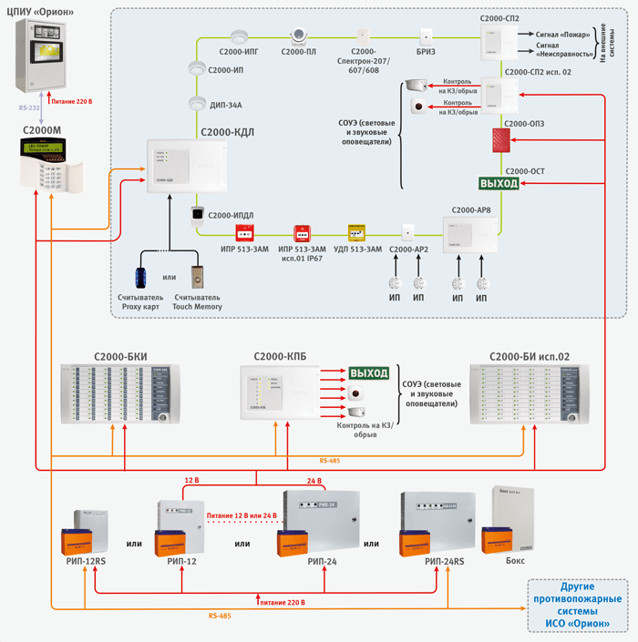
In Fig. An example of organizing an address-threshold fire alarm system using the Signal-10 block is given.

Addressable analogue fire alarm system in ISO "Orion" is built on the basis of a block-modular control panel, consisting of:
- Control and control panel “S2000M”;
- Two-wire communication line (BPK) controllers “S2000-KDL” or “S2000-KDL-2I”;
- Fire smoke optical-electronic addressable analogue detectors "DIP-34A";
- Fire thermal maximum-differential addressable analogue detectors “S2000-IP”;
- Fire addressable analogue gas and thermal maximum-differential fire detectors "S2000-IPG", designed to detect fires accompanied by the appearance of carbon monoxide in enclosed spaces, by monitoring changes chemical composition air and ambient temperature;
- Fire smoke optical-electronic linear addressable detectors “S2000-IPDL isp.60” (from 5 to 60 m), “S2000-IPDL isp.80” (from 20 to 80 m), “S2000-IPDL isp.100” (from 25 to 100 m), “S2000-IPDL isp.120” (from 30 to 120 m);
- Fire addressable thermal explosion-proof detectors “S2000-Spectron-101-Exd-M”, “S2000-Spectron-101-Exd-N”*;
- Fire addressable infrared (IR) flame detectors “S2000-PL”;
- Fire addressable infrared (IR) flame detectors “S2000-Spektron-207”;
- Multi-band addressable fire detectors (IR/UV) “S2000-Spectron-607-Exd-M” and “S2000-Spectron-607-Exd-H”*;
- Multi-band addressable fire detectors (IR/UV) “S2000-Spektron-607”;
- Multi-band (IR/UV) addressable fire detectors “S2000-Spektron-608”;
- Multi-band (IR/UV) explosion-proof addressable fire detectors “S2000-Spektron-607-Exi”*;
- Multi-band (IR/UV) explosion-proof addressable fire detectors “S2000-Spektron-608-Exi”*;
- Fire manual addressable call points “IPR 513-3AM”;
- Fire manual addressable call points with a built-in short circuit insulator “IPR 513-3AM isp.01” and “IPR 513-3AM isp.01” with a shell protection degree of IP67;
- Addressable remote start devices “UDP 513-3AM”, “UDP 513-3AM isp.01” and “UDP 513-3AM isp.02”, intended for manual start of fire extinguishing and smoke removal systems, unblocking emergency and evacuation exits;
- Fire detectors manual explosion-proof addressable "S2000-Spectron-512-Exd-N-IPR-A", "S2000-Spectron-512-Exd-N-IPR-B", "S2000-Spectron-512-Exd-M-IPR- A", "S2000-Spectron-512-Exd-M-IPR-B"*;
- Fire detectors manual explosion-proof addressable "S2000-Spectron-535-Exd-N-IPR", "S2000-Spectron-535-Exd-M-IPR" *;
- Explosion-proof addressable remote start devices “S2000-Spectron-512-Exd-N-UDP-01”, “S2000-Spectron-512-Exd-N-UDP-02”, “S2000-Spectron-512-Exd-N-UDP- 03", "S2000-Spectron-512-Exd-M-UDP-01", "S2000-Spectron-512-Exd-M-UDP-02", "S2000-Spectron-512-Exd-
- M-UDP-03"*;
- Explosion-proof addressable remote start devices “S2000-Spectron-535-Exd-N-UDP-01”, “S2000-Spectron-535-Exd-N-UDP-02”, “S2000-Spectron-535-Exd-N-UDP- 03", "S2000-Spectron-535-Exd-M-UDP-01", "S2000-Spectron-535-Exd-M-UDP-02", "S2000-Spectron-535-Exd-M-UDP-03" *;
- Branching and insulating blocks “BREEZ”, “BREEZ isp.01”, designed for isolating short-circuited sections with subsequent automatic recovery after the short circuit is removed. “BREEZE” is installed in the line as a separate device, “BREEZE isp.01” is built into the base of fire detectors “S2000-IP” and “DIP-34A”. Special versions of detectors “DIP-34A-04” and “IPR 513-3AM isp.01” with built-in short circuit insulators are also produced;
- Address expanders “S2000-AR1”, “S2000-AR2”, “S2000-AR8”. Devices designed for connecting non-addressable four-wire detectors. Thus, conventional threshold detectors, for example, linear detectors, can be connected to the addressable system;
- Alarm loop expansion units “S2000-BRShS-Ex”, designed for connecting non-addressable intrinsically safe detectors (see section “Explosion-proof solutions...”);
- Addressable radio expanders “S2000R-APP32”, designed for connecting radio channel devices of the “S2000R” series into a two-wire communication line;
- Devices of the S2000R series:
- Fire point smoke optical-electronic addressable analogue radio channel detectors “S2000R-DIP”;
- Fire thermal maximum-differential addressable analogue radio channel detectors “S2000R-IP”;
- Fire manual addressable call points "S2000R-IPR".
When organizing an addressable analogue fire alarm system, the devices “S2000-SP2” and “S2000-SP2 isp.02” can be used as relay modules. These are addressable relay modules, which are also connected to the S2000-KDL via a two-wire communication line. “S2000-SP2” has two relays of the “dry contact” type, and “S2000-SP2 isp.02” has two relays with monitoring the health of connection circuits actuators(separately for OPEN and SHORT CIRCUIT). For the S2000-SP2 relay, you can use operating tactics similar to those used in a non-addressable system.
The system also includes addressable security and fire sound sirens “S2000-OPZ” and light table address sirens “S2000-OST”. They are connected directly to the DPLS without additional relay units, but require a separate 12 - 24 V power supply.
The S2000R-APP32 radio expander allows you to control the S2000R-Siren light-sound radio channel siren. To control another fire load via a radio channel, the S2000R-SP unit is used, which has two controlled outputs.
Additionally, relay blocks “S2000-SP1” and “S2000-KPB” can be used to expand the number of system outputs; indication and control units “S2000-BI” and “S2000-BKI” for visual display of the status of inputs and outputs of devices and convenient control of them from the duty officer’s post.
The two-wire communication line controller actually has two alarm loops, to which a total of up to 127 addressable devices can be connected. These two loops can be combined to organize a ring structure of the DPLS. Addressable devices are fire detectors, addressable expanders or relay modules. Each addressable device occupies one address in the controller memory.
Address extenders occupy as many addresses in the controller’s memory as loops can be connected to them (“S2000-AP1” - 1 address, “S2000-AP2” - 2 addresses, “S2000-AP8” - 8 addresses). Addressable relay modules also occupy 2 addresses in the controller memory. Thus, the number of protected premises is determined by the addressable capacity of the controller. For example, with one “S2000-KDL” you can use 127 smoke detectors or 87 smoke detectors and 20 addressable relay modules. When addressable detectors are triggered or when addressable expander loops are disrupted, the controller issues an alarm notification via the RS-485 interface to the S2000M control panel. The “S2000-KDL-2I” controller functionally repeats the “S2000-KDL”, but has important advantage– galvanic barrier between the DPLS terminals and the power supply terminals, the RS-485 interface and the reader. This galvanic isolation will improve the reliability and stability of the system at facilities with complex electromagnetic environments. It also helps to exclude the flow of equalizing currents (for example, in case of installation errors), the influence of electromagnetic interference or interference from equipment used at the site or in the event external influences natural nature (lightning discharges, etc.).
For each addressable device in the controller, the input type must be specified. The input type indicates to the controller the tactics of the zone and the class of detectors included in the zone.
Type 2 - "Combined firefighter"
This type of input is intended for addressable expanders “S2000-AR2”, “S2000-AR8” and “S2000-BRShS-Ex” (see section “Explosion-proof solutions ...”), in which the controller will recognize CC states such as “Normal” , “Fire”, “Open” and “Short circuit”. For “S2000-BRSHS-Ex” the “Attention” state can be additionally recognized.
Possible input states:
- “Attention” – “S2000-BRShS-Ex” recorded the AL state corresponding to the “Attention” state;
- “Fire” – the address expander has recorded the AL state corresponding to the “Fire” state;
- “Break” – the address expander has recorded the loop state corresponding to the “Break” state;
- “Short circuit” – the address expander has recorded the AL state corresponding to the “Short circuit” state;
Type 3 - "Fire Thermal"
This type of input can be assigned to “S2000-IP” (and its modifications), “S2000R-IP” operating in differential mode, to “S2000-AP1” of various versions that control non-addressable fire detectors with a “dry contact” type output, as well as addressable detectors “S2000-PL”, “S2000-Spektron” and “S2000-IPDL” and all modifications. Possible input states:
- “Taken” – the input is normal and fully controlled;
- “Disabled (removed)” – the input is normal, only faults are monitored;
- “Failure to arm” – the controlled parameter of the control system was not normal at the time of arming;
- “Arming delay” – the input is in the arming delay state;
- “Fire” – the addressable heat detector has recorded a change in temperature corresponding to the condition for switching to the “Fire” mode (differential mode); the address expander recorded the CC state corresponding to the “Fire” state;
- “Fire2” – two or more inputs belonging to the same zone went into the “Fire” state in no more than 120 s. The "Fire2" state will also be assigned to all inputs associated with this zone that had the "Fire" state;
- “Fire equipment malfunction” – the measuring channel of the addressable heat detector is faulty.
Type 8 – “Smoke addressable analog”
This type of input can be assigned to “DIP-34A” (and its modifications), “S2000R-DIP”. In standby mode, the controller requests numerical values corresponding to the level of smoke concentration measured by the detector. For each input, pre-warning “Attention” and “Fire” warning thresholds are set. Trigger thresholds are set separately for the “NIGHT” and “DAY” time zones. Periodically, the controller requests the dust content value of the smoke chamber, the resulting value is compared with the “Dusty” threshold, which is set separately for each input. Possible input states:
- “Taken” – the entrance is normal and fully controlled, the thresholds “Fire”, “Attention” and “Dusty” are not exceeded;
- “Disabled (removed)” – only the “Dusty” threshold and faults are monitored;
- “Arming delay” – the input is in the arming delay state;
- “Failure to arm” – at the time of arming, one of the “Fire”, “Attention” or “Dusty” thresholds has been exceeded or a malfunction is present;
- “Fire2” – two or more inputs belonging to the same zone went into the “Fire” state in no more than 120 s. The "Fire2" state will also be assigned to all inputs associated with this zone that had the "Fire" state;
- “Fire equipment malfunction” – the measuring channel of the addressable detector is faulty;
- “Service required” – the internal threshold for automatic compensation of dust content in the smoke chamber of the addressable detector or the “Dusty” threshold has been exceeded.
Type 9 - "Thermal Addressable Analogue"
This type of input can be assigned to “S2000-IP” (and its modifications), “S2000R-IP”. In standby mode, the controller requests numerical values corresponding to the temperature measured by the detector. For each input, the temperature thresholds for the preliminary warning “Attention” and the warning “Fire” are set. Possible input states:
- “Arming delay” – the input is in the arming delay state;
- “Attention” – the “Attention” threshold has been exceeded;
- “Fire” – the “Fire” threshold has been exceeded;
- “Fire2” – two or more inputs belonging to the same zone went into the “Fire” state in no more than 120 s. The "Fire2" state will also be assigned to all inputs associated with this zone that had the "Fire" state;
Type 16 – "Firefighter manual"
This type of input can be assigned to “IPR 513-3A” (and its versions); "S2000R-IPR"; AL of address expanders. Possible input states:
- “Taken” – the input is normal and fully controlled;
- “Disabled (removed)” – the input is normal, only faults are monitored;
- “Failure to arm” – the controlled parameter of the control system was not normal at the time of arming;
- “Arming delay” – the input is in the arming delay state;
- “Fire2” – the addressable manual call point is switched to the “Fire” state (press the button); the address expander recorded the CC state corresponding to the “Fire” state;
- “Short circuit” – the address expander has recorded the CC state corresponding to the “Short circuit” state;
- “Fire equipment malfunction” – malfunction of the addressable manual call point.
Type 18 - "Fire Launcher"
This type of input can be assigned to addressable “UDP-513-3AM” and their versions; AL of address expanders with connected UDP. Possible input states:
- “Disabled (removed)” – the input is normal, only faults are monitored;
- “Arming delay” – the input is in the arming delay state;
- “Activation of the remote start device” – the UDP is switched to the active state (pressing the button); the address expander recorded the CC state corresponding to the “Fire” state;
- “Restoring the remote start device” – the UDP is transferred to its original state; the address expander recorded the CC state corresponding to the “Normal” state;
- “Break” – the address expander has recorded the CC state corresponding to the “Break” state;
- “Short circuit” – the address expander has recorded the CC state corresponding to the “Open” state;
- “Fire equipment malfunction” – EDU malfunction.
Type 19 – "Firefighter gas"
This type of input can be assigned to S2000-IPG. In standby mode, the controller requests numerical values corresponding to the carbon monoxide content in the atmosphere measured by the detector. For each input, pre-warning “Attention” and “Fire” warning thresholds are set. Possible input states:
- “Taken” – the input is normal and fully controlled, the “Fire” and “Attention” thresholds are not exceeded;
- “Disabled (removed)” – only faults are monitored;
- “Arming delay” – the input is in the arming delay state;
- “Failure to arm” – at the time of arming, one of the thresholds “Fire”, “Attention” has been exceeded or a malfunction is present;
- “Attention” – the “Attention” threshold has been exceeded;
- “Fire” – the “Fire” threshold has been exceeded;
- “Fire2” – two or more inputs belonging to the same zone went into the “Fire” state in no more than 120 s. The "Fire2" state will also be assigned to all inputs associated with this zone that had the "Fire" state;
- “Fire equipment malfunction” – the measuring channel of the addressable detector is faulty.
Additional parameters can also be configured for fire inputs:
- Automatic re-arming - instructs the device to automatically arm an unarmed alarm as soon as its resistance is normal within 1 s.
- Without the right to disarm – serves to enable permanent control of the zone, that is, a zone with this parameter cannot be disarmed under any circumstances.
- The arming delay determines the time (in seconds) after which the device attempts to arm the alarm after receiving the corresponding command. Non-zero “Arming Delay” in fire alarm systems is usually used if, before arming a non-addressed alarm loop, it is necessary to turn on the device output, for example, to reset the power supply to 4-wire detectors (relay control program “Turn on for a while before arming”).
The S2000-KDL controller also has a circuit for connecting readers. You can connect various readers operating via the Touch Memory or Wiegand interface. From the readers it is possible to control the state of the controller inputs. In addition, the device has functional indicators of the operating mode status, DPLS lines and an exchange indicator via the RS-485 interface. In Fig. An example of organizing an addressable analogue fire alarm system is given.
As mentioned above, the radio channel expansion of the addressable analogue fire alarm system, built on the basis of the S2000-KDL controller, is used for those premises of the facility where laying wire lines for one reason or another is impossible. The S2000R-APP32 radio expander provides constant monitoring of the presence of communication with 32 radio devices of the S2000R series connected to it and monitoring the status of their power supplies. Radio channel devices carry out automatic control the operability of the radio channel, and in case of high noise level, they automatically switch to the backup communication channel.
Operating frequency ranges of the radio channel system: 868.0-868.2 MHz, 868.7-869.2 MHz. The emitted power in transmission mode does not exceed 10 mW.
The maximum range of radio communication in open areas is about 300 m (the range of operation when installing a radio system indoors depends on the number and material of walls and ceilings in the path of the radio signal).
The system uses 4 radio frequency channels. At the same time, up to 3 “S2000R-APP32” can operate on each channel in the radio visibility zone. “S2000R-APP32” connects directly to the DPLS of the “S2000-KDL” controller and occupies one address in it. In this case, each radio device will also occupy one or two addresses in the S2000-KDL address space, depending on the selected operating mode.
The operating algorithms of radio devices are described above in the section devoted to the types of “S2000-KDL” inputs.

If it is necessary to equip a fire alarm for an object with explosive zones, together with an addressable analogue system built on the basis of the S2000-KDL controller, it is possible to use a line of specialized addressable explosion-proof detectors.
Multi-band flame detectors (IR/UV) “S2000-Spektron-607-Exd-...” (with special protection against false alarms for electric arc welding); thermal "S2000-Spectron-101-Exd-...", manual and UDP "S2000-Spectron-512-Exd-...", "S2000-Spectron-535-Exd-..." are manufactured in accordance with the requirements for explosion-proof equipment of the group I and subgroups IIA, IIB, IIC according to TR TS 012/2011, GOST 30852.0 (IEC 60079-0), GOST 30852.1 (IEC 60079-1) and correspond to the explosion protection marking РВ ExdI/1ExdIICT5. The explosion protection of these detectors is ensured by the shell. Thus, the DPLS line in a hazardous area must be made with an armored cable. The connection of the DPLS to the detectors is carried out through special cable entries. Their type is determined when ordering depending on the method of cable protection.
The shell of detectors marked – Exd-H is made of stainless steel. They are recommended to be installed at facilities with chemically aggressive environments (for example, petrochemical industry facilities).
For manual call points “S2000-Spektron-512-Exd-...” marking –B indicates the possibility of additional sealing of the detector using seals, and –A the absence of such a possibility.
According to the standards, detectors and UDP “S2000-Spectron-512-Exd-...” and “S2000-Spectron-535-Exd-...” can be used in the same way. Moreover, they have the same explosion protection markings and the same degree of protection of the internal volume by the shell. At the same time, detectors and UDP “S2000-Spectron-535-Exd-...” provide the maximum speed of issuing “Fire” signals (or control signal in the case of UDP). But they should not be used at sites where there is a possibility of unauthorized (accidental) activation of the device. Detectors and UDP “S2000-Spectron-512-Exd-...” have maximum protection against abnormal operations (including due to the presence of a seal). But because of this, the speed of issuing an alarm (control - in the case of UDP) signal to the system is somewhat reduced. They also have unique applications (for example, metal ore mines where magnetic anomalies are possible) due to the optoelectric operating principle. In addition, the products “S2000-Spectron-512-Exd-...” are somewhat more expensive.
For the operation of flame detectors in the area low temperatures(below - 40oC) there is a built-in thermostat - a device that, using heating elements, in automatic mode is capable of maintaining operating temperature inside the case. To operate the thermostat, an additional power source is required. Heating is turned on at a temperature of -20oC.
Multi-range flame detectors (IR/UV) "S2000-Spectron-607-Exi" (with special protection against false alarms for electric arc welding) and multi-range flame detectors (IR/UV) "S2000-Spectron-608-Exi" have an explosion protection level of "extra explosion-proof" » marked OExiaIICT4 X according to TR CU 012/2011, GOST 30852.0 (IEC 60079-0), GOST 30852.10 (IEC 60079-11). The explosion protection of these detectors is ensured by an intrinsically safe “ia” circuit and an antistatic shell. Connection to the DPLS is carried out using a conventional cable through the spark-proof barrier “S2000-Spectron-IB”, installed outside the hazardous area.
These detectors are recommended to be installed at gas stations, gas and oil refineries, and painting booths. For explosive areas, an explosion-proof multi-band (IR/UV) radio-channel flame detector “S2000R-Spektron-609-Exd” has been developed, connected to the expander “S2000R-APP32”.
Addressable explosion-proof detectors operate according to the “Fire Thermal” tactic. The algorithm of their operation is described above in the section devoted to the types of “S2000-KDL” inputs.
To connect other types of explosion-proof detectors, intrinsically safe barriers “S2000-BRShS-Ex” are used. This unit provides protection at the level of an intrinsically safe electrical circuit. This method of protection is based on the principle of limiting the maximum energy accumulated or released by an electrical circuit in emergency mode, or dissipating power to a level significantly below the minimum energy or ignition temperature. That is, the voltage and current values that can enter the danger zone in case of a malfunction. The intrinsic safety of the unit is ensured by galvanic isolation and the appropriate selection of the values of electrical clearances and creepage paths between intrinsically safe and associated intrinsically hazardous circuits, limiting voltage and current to intrinsically safe values in the output circuits through the use of compound-filled spark protection barriers on zener diodes and current-limiting devices, ensuring electrical clearances, leakage paths and integrity of spark protection elements, including due to their sealing (filling) with a compound.
"S2000-BRSHS-Ex" provides:
- receiving notifications from connected detectors via two intrinsically safe loops by monitoring their resistance values;
- power supply to external devices from two built-in intrinsically safe power supplies;
- relaying alarm messages to the two-wire communication line controller.
The X sign after the explosion protection marking means that only explosion-proof electrical equipment with the type of explosion protection “intrinsically safe electrical circuit i”, which has a certificate of conformity and a permit for use, is allowed to be connected to the connecting devices “S2000-BRShS-Ex” marked “intrinsically safe circuits”. Federal service on environmental, technological and nuclear supervision in explosive areas. “S2000-BRSHS-Ex” occupies three addresses in the address space of the “S2000-KDL” controller.
It is possible to connect any threshold fire detectors to the S2000-BRSHS-Ex. Today, the company ZAO NVP "Bolid" supplies a number of sensors for installation inside an explosive zone (explosion-proof version):
- "IPD-Ex" - optical-electronic smoke detector;
- "IPDL-Ex" - optical-electronic linear smoke detector;
- “IPP-Ex” - infrared flame detector;
- "IPR-Ex" - manual call point.
The “S2000-BRShS-Ex” inputs operate according to the “Combined Firefighter” tactic. The algorithm of their operation is described above in the section devoted to the types of “S2000-KDL” inputs.

When building distributed or large systems fire protection, in which more than one S2000M remote control is used, there is a need to combine local subsystems at the top level. For this purpose, the central display and control panel of the Orion TsPIU, certified according to GOST R 53325-2012, is intended. It is built on the basis of an industrial PC with redundant power with a special full-featured version of the Orion Pro automated workstation software installed on it and allows you to create a single automated workstation for indicating and controlling fire protection systems of individual buildings in residential areas, factories, and multifunctional complexes.
TsPIU "Orion" is installed in a room with round-the-clock presence of duty personnel, in which local network information from individual S2000M remote controls is compiled. That is, the TsPIU can simultaneously interrogate several subsystems, each of which is a control panel controlled by the S20000M remote control, and organize network interaction between them.
TsPIU "Orion" allows you to implement the following functions:
- Accumulation of PS events in the database (according to PS triggers, operator reactions to alarm events, etc.);
- Creating a database for a protected object - adding loops, sections, relays to it, arranging them on graphic plans of premises for monitoring and control;
- Creation of access rights for the functions of managing fire protection objects that duplicate the control panel (PPKUP) (resetting alarms, starting and blocking the start of automation and warning systems), assigning them to duty operators;
- Survey of control and monitoring devices connected to the control center;
- Registration and processing of fire alarms occurring in the system, indicating the reasons, service marks, as well as their archiving;
- Providing information about the state of PS objects in the form of an object card;
- Generating and issuing reports on various PS events.
Thus, the software used in the Orion TsPIU expands the functionality of the S2000M consoles, namely: it organizes interaction (cross-communications) between several consoles, maintains a general log of events and alarms of almost unlimited volume, allows you to specify the causes of alarms and log organizational actions of operators (calling the fire department, etc.), collect statistics of ADC analogue addressable detectors (dust, temperature, gas contamination) and smart power supplies with information interfaces.
Traditionally, it is technically possible to connect S2000M remote controls to a PC with an installed Orion Pro workstation. In this case, due to the lack of certification of the PC according to fire standards, the automated workplace will not be part of the control panel or control device. It can only be used as additional remedy dispatching (for redundant visualization, maintaining event logs, alarms, reporting, etc.), without control functions and organizing network interaction between several consoles.
The assignment of automatic fire alarm tasks to software modules is shown in Fig. 9. It is worth noting that the devices are physically connected to the system computer on which the Orion Pro Operational Task software module is installed. The device connection diagram is shown on the Orion ISO block diagram. The block diagram also shows the number of jobs that can be simultaneously used in the system (AWS software modules). Software modules can be installed on computers in any way - each module on a separate computer, a combination of any modules on a computer, or installing all modules on one computer.

The Orion TsPIU can be used in stand-alone mode or as part of an existing Orion Pro automated workstation. In the first case, the CPU will include the following modules: Server, Operational Task, Database Administrator and Report Generator. In the second of all the CPU modules, it is enough to use the Operational task, which will connect via a local network to a PC with an existing Server. In this case, the CPU will fully retain its functionality in the event of loss of connection or failure of the PC with the Server.
All devices intended for fire alarms in ISO "Orion" are powered from low-voltage power supplies (VPS) direct current. Most devices are adapted to a wide range of power supply voltages - from 10.2 to 28.4 V, which allows the use of sources with a nominal output voltage of 12 V or 24 V (Fig. 3-7). A personal computer with a dispatcher's workstation can occupy a special place in the fire alarm system. It is usually powered by an alternating current network, the stabilization and redundancy of which is provided by uninterruptible power supplies, UPS.
Distributed placement of equipment over a large facility, which is easily implemented in the Orion ISO, requires providing power to the devices at their installation sites. Taking into account the wide range of supply voltages, it is possible, if necessary, to place power supplies with an output voltage of 24V at a distance from consumer devices, even taking into account a significant voltage drop on the wires.
There are other power supply schemes in addressable analogue fire alarm systems based on the S2000-KDL controller. In this case, addressable detectors and relay modules S2000-SP2 connected to the two-wire signal communication line of the S2000-KDL controller will receive power via this line. With this power supply scheme, the controller itself and the “S2000-SP2 isp.02”, “S2000-BRShS-Ex” units will be powered from the power supply.
If we consider the case of radio expansion of an addressable analog system, then in accordance with clause 4.2.1.9 of GOST R 53325-2012, all radio devices have a main and backup autonomous power supply. At the same time, the average operating time of radio devices from the main source is 5 years and from the backup source is 2 months. "S2000-APP32" can be powered both from external source(9 -28 V) and from the DPLS, but due to the high current consumption of the device, in most cases it is recommended to use the first power supply circuit.
Basic normative document, which determines the parameters of the IE for fire alarms - . In particular:
1) The IE must have an indication:
Availability (within normal limits) of main and backup or standby power supplies (separately for each power supply input);
Availability of output voltage.
2) The IE must ensure the generation and transmission of information to external circuits about the absence of output voltage, input power supply voltage at any input, discharge of batteries (if any) and other faults controlled by the IE.
3) The IE must have automatic protection against short circuits and increases in output current above the maximum value specified in the TD for the IE. In this case, the IE should automatically restore its parameters after these situations.
4) Depending on the size of the object, powering the fire alarm system may require from one IE to several dozen power sources.
To power fire alarm systems there is a wide range of certified power supplies with an output voltage of 12 or 24 V, with a load current from 1 to 10A: RIP-12 isp.06 (RIP-12-6/80M3-R), RIP-12 isp. .12 (RIP-12-2/7M1-R), RIP-12 version 14 (RIP-12-2/7P2-R), RIP-12 version 15 (RIP-12-3/17M1-R), RIP-12 isp.16 (RIP-12-3/17P1-R), RIP-12 isp.17 (RIP-12-8/17M1-R), RIP-12 isp.20 (RIP-12-1/7M2 -R), RIP-24 isp.06 (RIP-24-4/40M3-R), RIP-24 isp.11 (RIP-24-3/7M4-R), RIP-24 isp.12 (RIP-24 -1/7M4-R), RIP-24 isp.15 (RIP-24-3/7M4-R)
These RIPs, designed to power fire automatic equipment, have information outputs: three separate relays, galvanically isolated from other circuits and from each other. The RIP monitors not only the presence or absence of input and output voltages, but also their deviations from the norm. Galvanic isolation of information outputs greatly simplifies their connection to any type of fire alarm and automation devices.
All devices and instruments included in the fire alarm system belong to the first category of power supply reliability category. This means that when installing a fire alarm, it is necessary to implement an uninterruptible power supply system. If the facility has two independent high-voltage power supply inputs, or the ability to use a diesel generator, then it is possible to develop and apply an automatic transfer switch (ATS) circuit. In the absence of such a possibility, uninterruptible power supply is forced to be compensated by redundant power supply using sources with a built-in or external low-voltage battery. In accordance with SP 513130-2009, the battery capacity is selected based on the calculated current consumption of all (or group) fire alarm devices, taking into account ensuring their operation at backup power in standby mode for 24 hours plus 1 hour in alarm mode. Also, when calculating the minimum battery capacity, it is necessary to take into account the operating temperature, discharge characteristics, and service life in buffer mode.
To increase the operating time of the RIP in backup mode, additional batteries (2 pcs.) can be connected to RIP-12 isp.15, RIP-12 isp.16, RIP-12 isp.17, RIP-24 isp.11, RIP-24 isp.15 .) with a capacity of 17A*h installed in Box-12 isp.01 (Box-12/34M5-R) for RIP with an output voltage of 12V and Box 24 isp.01 (Box-24/17M5-R) for RIP with an output voltage of 24V . These devices are presented in a metal case. These microprocessor-controlled products have protection elements against overcurrent, polarity reversal and battery overdischarge. Information is transmitted to the RIP about the state of each battery installed in the BOX using a two-wire interface. All cables for connecting the Box to the RIP are included in their delivery package.
At sites where they are presented special requirements To ensure the reliability of fire alarm operation, you can use power supplies with a built-in RS-485 interface: RIP-12 isp.50 (RIP-12-3/17M1-R-RS), RIP-12 isp.51 (RIP-12-3/17P1 -P-RS), RIP-12 isp.54 (RIP-12-2/7P2-R-RS), RIP-12 isp.56 (RIP-12-6/80M3-P-RS), RIP-12 isp. .60 (RIP-12-3/17M1-R-Modbus), RIP-12 isp.61 (RIP-12-3/17P1-R-Modbus), RIP-24 isp.50 (RIP-24-2/7M4 -Р-RS), RIP-24 isp.51 (RIP-24-2/7П1-P-RS), RIP-24 isp.56 (RIP-24-4/40М3-P-RS), RIP-48 isp. .01 (RIP-48-4/17M3-R-RS), which during operation continuously measure the network voltage, battery voltage, output voltage and output current, measure the battery capacity and transmit the measured values (on request) to the remote control S2000M or Orion Pro workstation. In addition, these sources provide thermal compensation of the battery charge voltage, thereby extending the service life of the battery. When using these power supplies, using the RS-485 interface, on the S2000M remote control or on a computer with an Orion Pro workstation, you can receive the following messages: “Network failure” (mains supply voltage below 150 V or above 250 V), “Power supply overload” ( RIP output current is more than 3.5 A), “Failure of the charger” (the charger does not provide voltage and current to charge the battery (AB) within the specified limits), “Failure of the power supply” (if the output voltage is below 10 V or above 14.5 V ), “Battery malfunction” (voltage (AB) is below normal, or its internal resistance is higher than the maximum permissible), “Battery alarm” (RPC case is open), “Output voltage cutoff”. RIP have light indication and sound signaling of events.
If there are no surge protection devices (SPDs) in the power supply circuit of the facility, or as an additional level of protection, it is recommended to install protective network units BZS or BZS isp.01, placing them directly near the network inputs of redundant power supplies or other equipment powered directly from AC mains 220V. In this case, to automatically restore the system’s functionality, BZS isp.01 is used.
To distribute the load current, suppress mutual interference between several consumer devices and protect against overloads on each of the 8 channels, it is recommended to use protective switching units BZK isp.01 and BZK isp.02.
For compact placement of fire alarm and automation devices on site, cabinets with redundant power supplies can be used: ShPS-12, ShPS-12 isp.01, ShPS-12 isp.02, ShPS-24, ShPS-24 isp.01, ShPS-24 isp.02.
These devices are metal cabinet, into which ISO “Orion” devices can be installed: “Signal-10”, “Signal-20P”, “S2000-4”, “S2000-KDL”, “S2000-KPB”, “S2000-SP1”, “S2000- PI" and others that can be mounted on a DIN rail. The devices can also be installed on the front door using additional DIN rails included in the MK1 mounting kit. ~220 V circuits are protected automatic switches. Two 12 V batteries with a capacity of 17 Ah are installed in the cabinet.
Inside the cabinet there are:
- power supply module MIP-12-3A RS with an output voltage of 12V and a current of 3A for “ShPS-12”;
- or power supply module MIP-24-2A RS with an output voltage of 24V and a current of 2A for “ShPS-24”;
- switching unit BK-12" or BK-24 which allow you to organize:
- seven power channels for devices with personal protection from overcurrent;
- connecting seven devices to the RS-485 interface line and a network controller to an output with “reinforced” protection for connecting external devices;
- automatic switches for overcurrent protection of power modules and additional connected consumers with a rated supply voltage of 220 V, 50 Hz.
ShPS-12 isp.01/ShPS-24 isp.01 are equipped with a window through which it is possible to visually monitor the devices installed inside. ShPS-12 isp.02/ShPS-24 isp.02 have a housing protection degree of IP54.

It has always been difficult to honestly ensure your well-being, but losing what you have righteously acquired in a fire or theft is a shame, and you need to earn money again... Security and fire alarm(OPS) allows you to reduce the risk of property loss due to misfortune to a minimum, and the rates of insurance premiums for housing equipped with it are significantly lower. Nowadays, another favorable circumstance has appeared - the installation of a fire alarm can be done by a person familiar with the basics of electrical engineering and household work, and the legalization of a correctly assembled system most often does not require compliance with complex formalities.
Really? OPS is a serious matter; the Ministry of Emergency Situations must respond to an alarm. And by law, the installation of a fire alarm must be carried out by a licensed organization, everyone knows this. Yes, but modern electronics have so simplified the construction of automatic security systems (AOS), while at the same time increasing their functionality and reliability, that, figuratively speaking, well-fed wolves vigilantly guard the grazing herd: professionals have a stable income, focusing exclusively on security functions, and citizens, without straining the budget, ensure their safety.
To understand why do-it-yourself security and fire alarm systems have become quite real, and how to do it correctly, let’s briefly take a look at the evolution of AOS, the design of their entirety and its component parts, and the principles of organizing security services for residential premises.
How AOS developed
Before chips and reed switches
Initially, AOS were built in the form of a chain of opening temperature sensors: spring contacts soldered with Wood or Rose alloys with a melting point of 70-86 degrees. The chain was forcibly closed manual call point with normally closed contacts. All this together formed a loop Ш. When heated, the solder melted, the contacts diverged, the circuit broke, the relay included in it, also with normally closed contacts, was released, its contacts closed and turned on an alarm. By pressing the detector button, it was possible to give an alarm manually.
Such systems at the very least worked as local ones, but for communication with the central control panel they required a long line (LAN), prone to faults and having its own leakage resistance, wire resistance, capacitance and inductance, which could cause both false operation and non-operation due to real danger .

Therefore, on the consoles they began to include rays - loops from the LS - into the diagonal of the electric bridge, and into its opposite diagonal - the balanced circuit of the BC (see figure). The beam was no longer characterized by the resistance of the loop R Ш, but by the total resistance (impedance) of the subscriber Z A. By adjusting the BC, we achieved equality of its impedance Z to the impedance of the subscriber Z A. Under this condition, the potentials in the diagonal of bridge 1-2 turned out to be equal, and the voltage U 1 -2 =0. When the sensor was triggered, U 1-2 >0 occurred, which triggered the alarm.
The AOC bridge circuit made it possible to make an important improvement: They began to turn on a resistor of a strictly defined value R Ш in parallel to the detector. This made it possible to judge the nature of the operation by the value of U 1-2: if R Ш remained in the circuit, then someone pressed the detector button, then U 1-2 will be approximately half the maximum ; This is an "Attention" signal. If the sensor opens, we will see a clear open circuit and a maximum of U 1-2; this is “Anxiety”.
Such a system was not very reliable: the slightest malfunction would give a false alarm, a team would come out, and then the fitter, expressing his thoughts on this matter in any form, would go to find and fix it. False alarms reduced the degree of trust in the AOS and from the order to the installer the facility remained open. Moreover, splashes of solder sometimes got between the open contacts, and the sensor, “squeaking,” calmed down again. There were cases when criminals shot at the sensors with an air gun through the window, and when they saw that the squad had left, they knew that they had at least an hour to “do the job.”
The BC also caused a lot of trouble: the drug parameters fluctuated greatly. An employee with an electrical engineering background was greeted by police and firefighters with with open arms, but often soon I had to sign a statement “on my own”: the salary was small (it doesn’t fit with a knife or bullets), and the hassle was no less than that of operas.
In large facilities consisting of many subscribers (department store, post office), beams from the premises were combined into a local console - control panel(PKP), which automatically gave an alarm over the telephone line when one of the beams was triggered. This made it possible to reduce the dependence of the BC on the state of the drugs, which were already under the control of the signalmen, but reduced reliability: having competently delved into the control panel, it was possible to disconnect the entire object from the remote control and operate there for your own pleasure.
At the same time, attempts were made to use parallel connection of sensors with thermobimetallic normally open contacts, shunted by R Ш. In theory, this would allow the value of U 1-2 to be used to judge from a remote control the location of the trigger, which a serial system does not allow. However, the open bimetal turned out to be extremely unreliable: the sensor with oxidized contacts did not announce itself in any way in advance, and then remained silent, like a fish on ice, when the fire was already blazing with all its might.
Reed switches
Sealed magnetically controlled contacts - reed switches - made the first revolution in AOS and OPS. Reed switches can withstand billions of operations without oxidizing the contact surfaces, and the problem of temperature operation was easily solved by using holding magnets made of materials with a Curie point of 70 degrees: when heated, the magnet stopped magnetizing and the contacts opened.
The principle of the reed switch allows it to be switched, which gives a reliable sensor suitable for both serial and parallel fire alarm systems. True, the accuracy of determining the trigger location using analog methods remained low, so parallel analog alarm systems did not become widespread. Nevertheless, it was thanks to reed switches that a fire alarm in the apartment appeared: the reliability and low cost of the sensors ensured the cost of the system, affordable even for the average Soviet consumer.
The “reed era” also includes the first smoke detectors, but by no means household ones: smoke triggering was ensured by ionization of the gap between the fixed contacts, for which it was illuminated by an ampoule with a radioactive isotope. Alarm installers were afraid of such sensors, in a thick steel case and marked with a radiation hazard sign, as if they were fire, and they were rarely used at particularly important facilities.
At the same time, PKPs also began to transform: the use of microcircuits with a medium degree of integration and analog-to-digital converters (ADCs) made it possible to simplify the BC or completely abandon them and measure the beam parameters directly. The first wireless control panels with autonomous power supply also appeared, which, regardless of telephone lines, gave an alarm to the remote control using the Altai system - the prototype of the modern mobile communications, invented in the USSR back in the 50s.
Chips and lasers
A real revolution in OPS was made and made publicly available by large integrated circuits (LSIs, chips) and miniature semiconductor lasers. This affected all links of the OPS, and the best of previous achievements organically fit into the new system (see the picture earlier in the text below).

Sensors using laser detectors monitor temperature and smoke in several parameters at once, which eliminates false alarms (see figure on the left). Some sensors combine the functions of motion detectors; they will be discussed below. “Smart” sensors can also be autonomous, equipped with a built-in battery.
The control panel of our days is a computerized device that can work both with “smart” junior colleagues and with old, but absolutely fail-safe and very cheap reed switches. This made it possible to include SPU in the household fire alarm systems - a signal and triggering device, which, based on a signal from the control panel or directly from the sensor, includes signboards, flashing lights, sirens and opens the valves of the automatic fire extinguishing system.
Modern alarm systems are digital-analog parallel-addressed: each sensor has its electronic address stitched into it, and the control panel knows exactly where everything happened. Using advanced software, analog sensors are also quite accurately controlled by loop parameters. The alarm signal is sent via GSM to the owner’s mobile phone and to the security company’s computer. The alarm can be duplicated directly from the chip sensor, and the activation of the control system can also be triggered from the gearbox.
Motion sensors on the same chips and infrared lasers have made the alarm systems truly security: they control the entire volume of the room or the area of the yard. The laser scanner signal is converted into a code, and the control panel processor continuously compares the codes one after another, filtering out interference from weather, precipitation, and small safe objects.
The capabilities of a modern fully functional security system are presented in the figure. This one is quite expensive, but the system is simpler, quite reliable for an apartment, and you can assemble it yourself. How will be described below, but for now let’s see what is needed and what can be achieved in general:

- An uninterruptible power supply (UPS) is necessary for the alarm system to continue to operate in a de-energized apartment;
- Universal sensor-announcers: on the left is a group of autonomous ones, for example. in the garage;
- Motion sensors;
- Electronic lock;
- Reed anti-burglary contactor;
- Sign board;
- Local alarm;
- Display with control panel;
- Automatic OPS.
Let's give some explanations. Firstly, reed tamper sensors are still in their place, not competing with motion sensors, and the point is not only in cheapness and reliability. The small reed contactor is easy to hide; its operation is not detected by the anti-scanner. The search for such a “bug” (and it is unknown whether it exists at all) with skillful installation requires so much time that hacking loses its meaning.
Secondly, instead of any of the devices in pos. 7, 8 can be connected to SPU. Thirdly, according to item 10: the power supply of the alarm system must be supplied from a separate circuit breaker turned on BEFORE the apartment one, otherwise reliable operation system is not guaranteed. And finally, a remote control with an access code display allows you to independently reset, test and reconfigure the alarm system.
Organizational structure
A radical improvement in the technical base also entailed improvements organizational structure OPS: subscribers rarely connect to the EMERCOM console; it is expensive and overloads both equipment and personnel. The role of signal concentrator was taken over by private security firms. It does not light up or is stolen everywhere and not always, and with an acceptable load they can gain a lot of subscribers, which provides a decent income for a small monthly fee.
This system is also beneficial for the owners: a private licensed security guard will be happy to advise, help with advice, and he has no experience in interacting with the Ministry of Emergency Situations and the police. And since the owner still pays him with his hard-earned money, it is easier to demand it if something happens than from a government agency.
Let's take care of the alarm
Do you need a project?
A fire alarm project is needed, and not so much for formal reasons. Only a security guard with extensive experience will be able to accurately indicate the location of devices, their types and connection diagram. Otherwise, the flame may rage beyond repair, and the attacker, immediately spotting the “homemade” (they are well versed in alarms), will only grunt and, having “bombed the hut,” will sit at ease in the owner’s favorite chair, drinking the owner’s cognac, smoking the owner’s cigar, gently stroking the bag on her knees, tightly stuffed with the owner's goods and looking ironically at the sensors in full combat readiness.
However, security companies, generally rightly believing that the main thing is real security, not paperwork, often make concessions to potential subscribers: they agree to do a cheaper project, a sketch, or limit themselves to an even cheaper consultation: where to install which sensors, where to place the alarm control panel, what cable and how to connect everything.
Then, after checking the work, they put him under guard, and based on the documents, they pass him by retroactively. The owner is no worse off for this: once the contract is signed and the apartment is already under control, the security guards bear all the responsibility. The components of a modern security system are completely reliable, Maintenance fire alarm comes down to periodic inspection its performance and readiness, which, together with the security company on duty, can be carried out by the owner himself, so, as a rule, there are no problems with service.
How to do what?
The law does not prohibit you from making an OPS yourself, but they won’t take one on the remote control. We will have to limit ourselves to displaying an alarm on a mobile phone, but this is already a serious help in misfortune: the Ministry of Emergency Situations and the police are obliged to respond to any signals from citizens. Therefore, we will describe which equipment to choose for which case, and how to correctly assemble it into a workable whole.
PKP
The types of modern control panels are shown in the figure. The first one on the left is a professional multi-beam analog-to-digital one. These can work with any security system schemes, connect in cascade, ensuring the protection of objects of any degree of complexity and conduct a dialogue with the computer of the security organization, recording and transmitting a complete picture of the development of the situation. They are not used in everyday life.

The next one is semi-professional, digital for parallel address fire alarm systems. It is shown open because From the outside it is a blank box. At the bottom right there is an individual entrepreneur; Next to it is a battery, quite powerful, apparently, for several hours, up to a day, autonomous operation.
On the top left is the electronic unit, and on empty space A control panel is located near it in 24-hour guarded premises, but it is usually placed further away. The fact is that the heart of the security system, although equipped with a self-defense system, is still the most vulnerable point of the security system. The work of the processor can be detected by a special scanner, similar to what car thieves do, and interfered with in a manner undesirable for the owner.
Therefore, the control panel is strongly recommended to be placed in a hidden, hard-to-reach and fairly well electrically shielded place, say, in a reinforced concrete basement. As for the RS482 serial interface, which connects the control panel and the remote control, its signals are very well encoded, and it is impossible to get through it to the processor.
Semi-professional PCP in everyday life is used in elite estates individually or collectively in residential complexes: one such control panel allows you to connect up to 255 sensors to it.
The next one is a multi-beam household control panel. This is a device that is already affordable for the average citizen. This device is intended for private households with outbuildings: in addition to servicing reed switches and chip wire beams, it can process signals from 2-8, depending on the model, wireless sensors.
The one on the far right is the simplest apartment control panel. The cheapest models serve only one beam (you don’t need more in an apartment), but, like all of the above, they can transmit a signal to a mobile number. The number in inexpensive household control panels without access using a code from your own remote control is updated upon purchase or from a security company, so you need to keep the phone with it charged and with a valid account: mobile operators charge a fee for receiving messages via GSM.
Household alarm control panels are necessarily equipped with detailed instructions with typical fire alarm circuit diagrams, a list of types and models of sensors compatible with the device, and recommendations for installing the system. Often the kit includes a flashing beacon for front door and a “Protected facility” sticker. These are very useful additions: their presence most often forces villains and vandals to go away.
The control panel must comply with the European standard EN54, which is ensured by SSPB, LPCB or VdS certificates.
Sensors
Sensors and their connecting wires are the key component of the alarm system, which determines its reliability as a whole. First of all, about the wires. Sensors are no longer connected using telephone “noodles”, fragile and unreliable: on sale there are many types of signal two- and multi-core cables in a round outer sheath, which can be laid along the walls so as not to be conspicuous, and hidden under decorative sheathing. But we should talk in more detail about the sensors themselves.
Choice

For apartment best option– good old reed caps, see fig. For the kitchen, it is desirable to have a chip one that reacts, in addition to heat, to smoke. If significant valuables are stored in the apartment, then it is better to install fully functional ones with motion detectors near their locations.
In a private house, a motion sensor in the yard with a built-in control system loaded onto a lighting lantern would be useful. And it will scare away uninvited guests, and you won’t have to stumble in the dark: the SPU will illuminate you.
Multifunctional sensors are necessarily equipped with an indicator LED, while the simplest ones can be with or without it. The first is preferable: the glow or, conversely, the extinguishing of the indicator indicates a malfunction of the sensor. If there is a false alarm, there is no need to climb the ceiling with the tester - the bad sensor is immediately visible.
Accommodation

At first glance, the standards for placing OPS sensors are very liberal, see Fig.: no further than 4.5 m from a wall or corner and no more than 9 m between sensors. But this was done only for the convenience of configuring a specific OPS, but in fact the placement of sensors is a delicate matter.
Firstly, when placing them on walls, there must be at least 0.2 m to the ceiling, otherwise the sensor may end up in a smoke pocket and give a false alarm. Have you seen smoky rooms? The upper corners are the most smoky there. Secondly, with beams on the ceiling, the sensors need to be placed on their lower surfaces, and not on the sides or in the space between the beams, for the same reason.
And finally, the sensor does not survey the entire hemisphere, and its sensitivity depends on the distance to the source of danger. The controlled area in the form of a circle in an empty room depends on the ceiling height as follows:
- Up to 3.5 m – up to 85 sq. m.
- 3.5-6 m – up to 70 sq. m.
- 6-10 m – up to 65 sq. m.
- From 10 m – up to 55 sq. m.
By flame:
- Up to 3.5 m – up to 25 sq. m.
- 3.5-6 m – up to 20 sq. m.
- 6-9 m – up to 15 sq. m.
- Over 9 m – not controlled; the fire will become a fire before the detector is triggered.
“Before” in front of the area means that this is the maximum achievable value - in an empty room with proportions in a 3/4 plan. Accurate calculation of the location of sensors in habitable rooms requires computer modeling or the eye of an experienced specialist. If the alarm system is done independently without output to the security console, then we can assume that one sensor in the living room “sees” below a square with side L equal to the ceiling height of up to 4 m. The outermost sensors should be placed at half this distance from the nearest wall, and the intermediate ones – at a distance L from each other. In long and narrow rooms, the main consideration is the distance between the sensors.
Example: corridor in Khrushchev 1.75x4 m; ceiling height - 2.5 m. Two sensors are needed, located 1.75/2 = 0.875 from the end walls. In the bedroom of the same Khrushchev building 2.5x4.5 m, two sensors are also needed 1.25 m from the end walls.
Connection

Fire alarm sensors are connected strictly according to their instructions. The beam loop always ends with a termination resistor R. Its value is indicated in the instructions for the control panel. Default R=470 ohms, but ratings of 680 ohms or 910 ohms may be required. Let us explain in more detail only two frequently requested points.
First– inclusion of five-terminal IP-212 sensors, which have proven themselves, in a two-wire loop. How to do this is shown in the figure on the left.

Second– connection of conventional sensors with one terminal block. The cable wires must enter/exit the terminal block in a MIRROR way, as shown in Fig. on right.
Third– sensors with two terminal blocks. The left block is for the CABLE, which is connected according to the instructions or as described. But the right one should be dealt with before purchasing: it is intended for autonomous activation of the SPU; Some of the most common circuits of such sensors are shown in the last figure.
If the contacts of the loop (terminals 1-4) and the SPU (terminals 6-8) are electrically separated, as in the rightmost position, then you need to find out the permissible voltage and current or power of the SPU. If the contact is common, as in the other three positions, then the voltage is 12 V at a current of up to 200 mA, and it will go to the SPU from the loop, i.e. load the sensor with light bulbs, bells, etc. you can’t - the control panel will fail.
Today, facility security systems are becoming very popular. To increase the level of protection, integrated security systems are most often installed. Security and fire alarm systems are one of such complexes. Thanks to its component composition and versatility, it is possible to identify the source of fire in time and control access to the protected area. Fire-fighting equipment is quite complex and, of course, expensive, but more reliable electronic device there is no protection.
Components of equipment for fire and security systems
Fire alarm is considered a necessary condition security in any enterprise. In order to understand the principle of its functioning, you need to know what it consists of. It is equipped with the following devices:
- Sensors that can detect the occurrence of open fire or smoke in the room;
- Mechanisms for collecting information from sensors or control panels;
- Security management programs (computer or computer network with specialized software).
Main aspects in the work of the security guards
The principle of operation of fire and security alarms is quite simple and understandable. The receiving devices are detectors, which are equipped with various types of sensors. Information about the fire received by the sensor mechanisms (sensors) is transmitted to the data collection device (control panel). In more complex systems, where control is carried out in a centralized manner, information is transmitted to a central control panel (computer). The software embedded in the PC makes a decision, depending on the information received, and puts the system into action.
To understand the operating principle of the protective circuit, close attention must be paid to the notification devices. They are divided into active and passive.
Active ones operate on the principle of a constant signal. If it changes, the sensor will transmit a message about the fire extinguishing function to the control panel. Passive ones respond to changes in the external environment, for example: an increase in temperature in the area of the protected object. Depending on the influencing factor, the principle of operation of the fire alarm may differ.
The diagram shows how this equipment works. If a situation arises that threatens the life and health of people, an alert occurs using a special sound signal. Often, in addition to the sound signal, special light signs are installed to help a person find an emergency exit in smoke conditions.
Further, if the room is equipped with an access control system, a signal is sent to the actuators: electromechanical lock, gates, barriers, airlock cabins, turnstiles, etc. They open the emergency exit doors for people to quickly and unhinderedly leave the area where an emergency has occurred.
If the object is equipped with an automatic fire extinguishing system, then it will definitely work. At the same time, the smoke removal function is activated.
Automatic fire extinguishing installations are equipped with control systems engineering structures, communications and air conditioning lines.
An important point inherent in the algorithm of actions when a fire alarm is triggered is the fact that the power supply to the facility must be turned off, while the security system automatically switches to an uninterruptible power supply, that is battery. The connection diagram always comes with the alarm kit, but its connection must be entrusted to specialists licensed to install and maintain the system, as this guarantees the correct and continuous operation of the equipment.
Video about fire safety:
What is a fire protection equipment wiring diagram?
The schematic diagram for connecting fire-fighting equipment is a graphical representation of the location of devices and mechanisms in the room. It definitely includes symbols and a plan for laying connecting circuits. All security and fire systems are electrical, so their connection must strictly comply with the diagram. As a rule, it consists of the following mechanisms:
- Notification devices;
- Reception station;
- Backup power supply unit;
- Main power supply;
- Switching subsystem;
- Wiring (connecting lines);
- Fire extinguishing actuators.

The history of the development of security alarms goes back much more years than is commonly believed. An example is the ancient diagrams of original inventions, such as the Japanese “singing floors”, the “Dionysian ear” from ancient Greece, or the Egyptian secret traps designed to ensure the safety of the treasures of the pharaohs. The first prototypes of modern security alarms began to be developed along with the advent of photocells and the electric bell.
Modern technologies provide the opportunity to choose a security alarm among a variety various options. Such systems use a variety of types and combinations of equipment. However, in this diversity there is a common logic, and therefore it is possible to describe a general simple security alarm system, which allows us to get a certain idea of its design and operating principles.
The equipment diagram of any security alarm system includes the following components.
Security alarm detectors. Depending on the project, different types of detectors can be used. The most common options are infrared (passive or active), photoelectric, magnetic contact, and detectors that respond to sound, glass breakage or temperature changes.
Controller. This is a key component of a security alarm system, collecting and analyzing signals from all detectors in the system, and also triggering it when strangers enter the protected area. At the same time, the controller displays information about the incident on the display or other data display device.
Executive device. By using of this element the system reacts to a violation of the security circuit. Modern alarm systems are equipped with a variety of actuators, including audio (sirens, bells, loudspeakers), communication (notifying an alarm via radio or cellular communication), visual (light panels, flashing beacons) or active ones, for example, blocking exits and elevators.
Power supplies and communication lines. These elements serve for power supply (including autonomous) and communication between the elements of the security system.
A typical security alarm circuit looks like this.
Active infrared motion detectors and passive magnetic reed switches are used as detectors, triggering the system when the doors are opened. Actuating devices are sound and visual (light) indicators (flashlight, siren). The control panel contains components for controlling the security alarm, LED indicators that signal in the background about the integrity of the circuit, as well as a special relay that triggers actuator mechanisms when the contacts on it are closed. The system is supplied with electricity using a 12-volt uninterruptible power supply. As a rule, security alarms have an autonomous power supply, since dependence on the central network increases their vulnerability to intruders.
Having a general understanding of the principle of construction and operation of the security alarm system, this scheme can be modified and finalized using various methods, For example:
- increasing the number of security system circuits that are independent of each other;
- combining detectors of different types and optimizing their localization. In this case, the main task is to eliminate “blind spots” and provide backup scenarios for triggering the security circuit;
- providing additional levels of security, such as backup power supplies for alarms, or methods for quickly restoring the functionality of the security system in the event of a disruption in communication channels;
- integrating burglar alarms with other security systems such as video surveillance, patrol services, fire fighting equipment etc.
- complementing the functions with active security measures that influence violators. Paralyzing gas released into the room through ventilation ducts, floor hatches leading directly into the piranha pool and other techniques from adventure films are extreme examples of such mechanisms. However, security measures that are not so exotic and dangerous, but similar in principle of operation, are often used in reality.
In the vast majority of cases, measures that complicate the security system are aimed at increasing its reliability and ability to withstand any known methods unnoticed penetration or direct intrusion into a protected area. Violators, in turn, are trying to develop effective, fast and invisible ways to bypass all levels of protection.
In any case, this is another version of the confrontation between offensive and defensive means, in which each side must develop continuously so as not to give the advantage to the enemy. For this reason, new technologies and technologies will be constantly developed in the field of security alarms in the future. innovative equipment. At the same time, the basic design of security systems will remain unchanged.
The UNITEST company specializes in the manufacture of security and fire safety equipment, as well as the design of security systems.
Fire alarm circuit designed taking into account architectural features building, will allow the most rational and efficient placement of equipment for timely identification and localization of the source of fire. The fire alarm system should include a fire extinguishing system, building ventilation control, and possibly voice warning and elevator operation control.
The security alarm circuit is used to develop a system to prevent unauthorized entry into the building by unauthorized persons. The signaling scheme takes into account cable routing, installation of sensors, control panels and placement of the control system. It is important that the placement of the system minimizes damage to the interior finish of the building. This factor must also be taken into account in the diagram.
The fire and security alarm scheme is designed to take into account the location of the integrated security system. It reflects signaling devices, fire extinguishing devices, control units, as well as the location of the access office and video surveillance systems. The scheme is developed taking into account the individual characteristics of the protected object - calculated required amount sensors and devices for powder, gas or water fire extinguishing.
UNITEST company - indispensable assistant in the development of security and fire alarm systems. All products are certified and designed to serve your safety.