Bending deformation consists in curvature of the axis of a straight rod or in a change in the initial curvature of a straight rod (Fig. 6.1). Let's get acquainted with the basic concepts that are used when considering bending deformation.
Rods that bend are called beams.
Clean called bending, in which the bending moment is the only internal force factor arising in the cross section of the beam.
More often, in the cross section of the rod, along with the bending moment, a transverse force also arises. This bending is called transverse.
Flat (straight) called bending when the plane of action of the bending moment in the cross section passes through one of the main central axes of the cross section.
At oblique bend the plane of action of the bending moment intersects the cross section of the beam along a line that does not coincide with any of the main central axes of the cross section.
We begin our study of bending deformation with the case of pure plane bending.
Normal stresses and strains during pure bending.
As already mentioned, with pure plane bending in the cross section, of the six internal force factors, only the bending moment is nonzero (Fig. 6.1, c):
Experiments carried out on elastic models show that if a grid of lines is applied to the surface of the model (Fig. 6.1, a), then with pure bending it deforms as follows (Fig. 6.1, b):
a) longitudinal lines are curved along the circumference;
b) contours cross sections remain flat;
c) the contour lines of the sections intersect everywhere with the longitudinal fibers at right angles.
Based on this, it can be assumed that in pure bending, the cross sections of the beam remain flat and rotate so that they remain normal to the curved axis of the beam (flat sections in bending hypothesis).

Rice. 6.1
By measuring the length of the longitudinal lines (Fig. 6.1, b), you can find that the upper fibers lengthen when the beam bends, and the lower ones shorten. Obviously, it is possible to find fibers whose length remains unchanged. A set of fibers that do not change their length when a beam is bent is called neutral layer (n.s.). The neutral layer intersects the cross section of the beam in a straight line, which is called neutral line (n.l.) section.
To derive a formula that determines the magnitude of normal stresses arising in the cross section, consider a section of the beam in a deformed and undeformed state (Fig. 6.2).

Rice. 6.2
Using two infinitesimal cross sections, we select an element of length  . Before deformation, sections bounding the element
  , were parallel to each other (Fig. 6.2, a), and after deformation they bent slightly, forming an angle
  . The length of the fibers lying in the neutral layer does not change when bending
  . Let us denote the radius of curvature of the trace of the neutral layer on the drawing plane by the letter
  . Let us determine the linear deformation of an arbitrary fiber
  , located at a distance
  from the neutral layer.
The length of this fiber after deformation (arc length  ) is equal to
  . Considering that before deformation all fibers had the same length
  , we find that the absolute elongation of the fiber under consideration
Its relative deformation 

It's obvious that  , since the length of the fiber lying in the neutral layer has not changed. Then after substitution
  we get
 (6.2)
(6.2)
Therefore, the relative longitudinal strain is proportional to the distance of the fiber from the neutral axis.
Let us introduce the assumption that when bending, the longitudinal fibers do not press on each other. Under this assumption, each fiber is deformed in isolation, experiencing simple tension or compression, in which  . Taking into account (6.2)
 , (6.3)
that is, normal stresses are directly proportional to the distances of the cross-section points under consideration from the neutral axis.
Let us substitute dependence (6.3) into the expression for the bending moment  in cross section (6.1)
 .
.
Recall that the integral  represents the moment of inertia of the section relative to the axis
 .
.
 (6.4)
(6.4)
Dependence (6.4) represents Hooke's law for bending, since it relates the deformation (curvature of the neutral layer  ) with a moment acting in the section. Work
  is called the section stiffness during bending, N m 2.
Let's substitute (6.4) into (6.3)
 (6.5)
(6.5)
This is the required formula for determining normal stresses during pure bending of a beam at any point in its cross-section.
In order to establish where the neutral line is located in the cross section, we substitute the value of normal stresses into the expression for the longitudinal force  and bending moment

Because the  ,
,
 ;
;
 (6.6)
(6.6)
 (6.7)
(6.7)
Equality (6.6) indicates that the axis  – neutral axis of the section – passes through the center of gravity of the cross section.
Equality (6.7) shows that  And
And  - the main central axes of the section.
According to (6.5), the highest voltage is achieved in the fibers furthest from the neutral line

Attitude  represents the axial moment of resistance of the section
  relative to its central axis
  , Means

Meaning  for the simplest cross sections the following:
For rectangular cross section
 , (6.8)
Where  - side of the section perpendicular to the axis
  ;
;
 - side of the section parallel to the axis
  ;
;
For round cross section
 , (6.9)
Where  - diameter of the circular cross-section.
The strength condition for normal bending stresses can be written in the form
 (6.10)
All formulas obtained were obtained for the case of pure bending of a straight rod. The action of the transverse force leads to the fact that the hypotheses underlying the conclusions lose their strength. However, calculation practice shows that even during transverse bending of beams and frames, when in the section, in addition to the bending moment  there is also a longitudinal force
  and shear force
  , you can use the formulas given for pure bending. The error is insignificant.
In engineering and civil engineering sciences (strength of materials, structural mechanics, strength theory), a beam is understood as an element of a supporting structure that is susceptible primarily to bending loads and has various shapes cross section.
Of course, in real construction, beam structures are also subject to other types of loading (wind load, vibration, alternating loading), however, the main calculation of horizontal, multi-supported and rigidly fixed beams is carried out under the action of either transverse or equivalent load reduced to it.
The calculation scheme considers the beam as a rigidly fixed rod or as a rod mounted on two supports. If there are 3 or more supports, the rod system is considered statically indeterminate and the deflection of both the entire structure and its individual elements, becomes much more complicated.
In this case, the main load is considered as the sum of forces acting in the direction perpendicular to the section. The purpose of the deflection calculation is to determine the maximum deflection (deformation) which should not exceed the limit values and characterizes the rigidity of both an individual element (and the entire building structure associated with it.
Basic provisions of calculation methods
 Modern construction methods for calculating rod (beam) structures for strength and rigidity make it possible, already at the design stage, to determine the value of the deflection and make a conclusion about the possibility of operating the building structure.
Calculation of rigidity allows us to resolve the issue of the greatest deformations that may occur in a building structure during complex action various types loads
Modern calculation methods, carried out using specialized calculations on electronic computers, or performed using a calculator, make it possible to determine the rigidity and strength of the research object.
Despite the formalization of calculation methods, which involve the use of empirical formulas, and the effect of real loads is taken into account by introducing correction factors (safety factors), a comprehensive calculation quite fully and adequately assesses the operational reliability of a constructed structure or a manufactured element of a machine.
Despite the separateness of strength calculations and determination of structural rigidity, both methods are interrelated, and the concepts of “rigidity” and “strength” are inseparable. However, in machine parts, the main destruction of an object occurs due to loss of strength, while structural mechanics objects are often unsuitable for further use due to significant plastic deformations, which indicate low rigidity of structural elements or the object as a whole.
Today, in the disciplines “Strength of Materials”, “Structural Mechanics” and “Machine Parts”, two methods of calculating strength and stiffness are accepted:
- Simplified(formal), during which aggregated coefficients are used in calculations.
- Refined, where not only safety factors are used, but also contraction is calculated based on limit states.
Stiffness calculation algorithm

Formula for determining the bending strength of a beam
- M– the maximum moment occurring in the beam (found from the moment diagram);
- Wn,min– moment of resistance of the section (found from the table or calculated for a given profile), the section usually has 2 moments of resistance of the section, Wx is used in the calculations if the load is perpendicular to the axis x-x profile or Wy if the load is perpendicular to the y-y axis;
- Ry– design resistance of steel in bending (set in accordance with the choice of steel);
- γc– working conditions coefficient (this coefficient can be found in Table 1 SP 16.13330.2011;
The algorithm for calculating rigidity (determining the amount of deflection) is quite formalized and is not difficult to master.
In order to determine the deflection of the beam, it is necessary to perform the following steps in the sequence below:
- Draw up a calculation scheme object of research.
- Determine dimensional characteristics beams and design sections.
- Calculate maximum load, acting on the beam, determining the point of its application.
- If necessary, the beam (in the design scheme it will be replaced by a weightless rod) is additionally checked for strength by the maximum bending moment.
- The value of the maximum deflection is determined, which characterizes the stiffness of the beam.
To draw up a design diagram of a beam, you need to know:
- Geometric dimensions of the beam, including the span between the supports, and if there are consoles, their length.
- Geometric shape and cross-sectional dimensions.
- Load nature and their application points.
- Beam material and its physical and mechanical characteristics.
In the simplest calculation of two-support beams, one support is considered rigid, and the second is hinged.
Determination of moments of inertia and section resistance
The geometric characteristics that are necessary when performing strength and stiffness calculations include the moment of inertia of the section (J) and the moment of resistance (W). To calculate their values, there are special calculation formulas.

Section modulus formula
When determining the moments of inertia and resistance, it is necessary to pay attention to the orientation of the section in the cut plane. As the moment of inertia increases, the rigidity of the beam increases and the deflection decreases. This can be easily checked in practice by trying to bend the board in its normal, “lying” position and placing it on its edge.
Determination of maximum load and deflection

Formula for determining deflection
- q– uniformly distributed load, expressed in kg/m (N/m);
- l– beam length in meters;
- E– modulus of elasticity (for steel equal to 200-210 GPa);
- I– moment of inertia of the section.
When determining the maximum load, it is necessary to take into account a fairly significant number of factors acting both constantly (static loads) and periodically (wind, vibration shock load).
IN one-story house, on wooden beam ceiling there will be constant weight forces from its own weight, the partitions located on the second floor, furniture, occupants, and so on.
Features of deflection calculations
Of course, the calculation of floor elements for deflection is carried out for all cases and is mandatory in the presence of a significant level of external loads.
Today, all calculations of the deflection value are quite formalized and all complex real loads are reduced to the following simple calculation schemes:
- Kernel, resting on a fixed and hinged support, perceiving a concentrated load (the case is discussed above).
- Kernel, resting on a fixed and hinged structure on which a distributed load acts.
- Various loading options rigidly fixed cantilever rod.
- Action on a design object of a complex load– distributed, concentrated, bending moment.
At the same time, the calculation method and algorithm do not depend on the material of manufacture, the strength characteristics of which are taken into account different meanings modulus of elasticity.
The most common mistake is usually undercounting units of measurement. For example, power factors in calculation formulas are substituted in kilograms, and the value of the elastic modulus is taken according to the SI system, where there is no concept of “kilogram of force”, and all forces are measured in newtons or kilonewtons.
Types of beams used in construction
The modern construction industry, when constructing industrial and residential structures, practices the use of rod systems of various sections, shapes and lengths, made of various materials.
The most widespread are steel and wooden crafts. Depending on the material used, determining the deflection value has its own nuances related to the structure and uniformity of the material.
Wooden

Modern low-rise construction individual houses And country cottages practices widespread use of logs made from softwood and hardwood.
Basically, wooden products that work in bending are used for arranging floors and ceilings. It is these structural elements that will experience the greatest lateral loads, causing the greatest deflection.
Deflection boom wooden logs depends:
- From material(species of wood) that was used to make the beam.
- From geometric characteristics and the shape of the cross-section of the design object.
- From cumulative action various types of loads.
The criterion for the permissibility of beam deflection takes into account two factors:
- Correspondence to real deflection maximum permissible values.
- Possibility of using the structure in the presence of a calculated deflection.
Steel

They have a more complex cross-section, which can be composite, made from several types of rolled metal. When calculating metal structures, in addition to determining the rigidity of the object itself and its elements, it often becomes necessary to determine the strength characteristics of the connections.
Typically, the connection of individual elements of a steel structure is carried out:
- By using threaded(stud, bolt and screw) connections.
- Connection with rivets.
Bending is a type of deformation in which the longitudinal axis of the beam is bent. Straight beams that bend are called beams. Direct bending is a bend in which the external forces acting on the beam lie in one plane (force plane) passing through the longitudinal axis of the beam and the main central axis of inertia of the cross section.
The bend is called pure, if only one bending moment occurs in any cross section of the beam.
Bending, in which a bending moment and a transverse force simultaneously act in the cross section of a beam, is called transverse. The line of intersection of the force plane and the cross-sectional plane is called the force line.
Internal force factors during beam bending.
During plane transverse bending, two internal force factors arise in the beam sections: transverse force Q and bending moment M. To determine them, the method of sections is used (see lecture 1). The transverse force Q in the beam section is equal to the algebraic sum of the projections onto the section plane of all external forces, acting on one side of the section under consideration.
Rule of signs for shear forces Q:

The bending moment M in a beam section is equal to the algebraic sum of the moments relative to the center of gravity of this section of all external forces acting on one side of the section under consideration.
Sign rule for bending moments M:

Zhuravsky's differential dependencies.
Differential relationships have been established between the intensity q of the distributed load, the expressions for the transverse force Q and the bending moment M:

Based on these dependencies, the following general patterns of diagrams of transverse forces Q and bending moments M can be identified:

Features of diagrams of internal force factors during bending.
1. In the section of the beam where there is no distributed load, the Q diagram is presented straight line , parallel to the base of the diagram, and diagram M - an inclined straight line (Fig. a).
2. In the section where a concentrated force is applied, Q should be on the diagram leap , equal to the value of this force, and on the diagram M - breaking point (Fig. a).
3. In the section where a concentrated moment is applied, the value of Q does not change, and the diagram M has leap , equal to the value of this moment (Fig. 26, b).
4. In a section of a beam with a distributed load of intensity q, the diagram Q changes according to a linear law, and the diagram M changes according to a parabolic law, and the convexity of the parabola is directed towards the direction of the distributed load (Fig. c, d).
5. If, within a characteristic section, the diagram Q intersects the base of the diagram, then in the section where Q = 0, the bending moment has an extreme value M max or M min (Fig. d).
Normal bending stresses.
Determined by the formula:

The moment of resistance of a section to bending is the quantity:

Dangerous cross section during bending, the cross section of the beam in which the maximum normal stress occurs is called.
Shear stresses during straight bending.
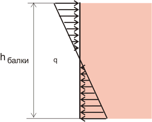
Determined by Zhuravsky's formula for shear stresses at straight bend beams:

where S ots is the static moment of the transverse area of the cut-off layer of longitudinal fibers relative to the neutral line.
Calculations of bending strength.
1. At verification calculation The maximum design stress is determined and compared with the permissible stress:

2. At design calculation the selection of the beam section is made from the condition:

3. When determining the permissible load, the permissible bending moment is determined from the condition:
![]()
Bending movements.
Under the influence of bending load, the axis of the beam bends. In this case, tension of the fibers is observed on the convex part and compression on the concave part of the beam. In addition, there is a vertical movement of the centers of gravity of the cross sections and their rotation relative to the neutral axis. To characterize bending deformation, the following concepts are used:
Beam deflection Y- movement of the center of gravity of the cross section of the beam in the direction perpendicular to its axis.
Deflection is considered positive if the center of gravity moves upward. The amount of deflection varies along the length of the beam, i.e. y = y(z)

Section rotation angle- angle θ through which each section rotates relative to its original position. The rotation angle is considered positive when the section is rotated counterclockwise. The magnitude of the rotation angle varies along the length of the beam, being a function of θ = θ (z).

The most common methods for determining displacements is the method Mora And Vereshchagin's rule.
Mohr's method.
The procedure for determining displacements using Mohr's method:
1. An “auxiliary system” is built and loaded with a unit load at the point where the displacement is required to be determined. If linear displacement is determined, then a unit force is applied in its direction; when angular displacements are determined, a unit moment is applied.
2. For each section of the system, expressions for bending moments M f from the applied load and M 1 from the unit load are written down.
3. Over all sections of the system, Mohr’s integrals are calculated and summed, resulting in the desired displacement:

4. If the calculated displacement has positive sign, this means that its direction coincides with the direction of the unit force. A negative sign indicates that the actual displacement is opposite to the direction of the unit force.
Vereshchagin's rule.
For the case when the diagram of bending moments from a given load has an arbitrary outline, and from a unit load – a rectilinear outline, it is convenient to use the graphic-analytical method, or Vereshchagin’s rule.

where A f is the area of the diagram of the bending moment M f from a given load; y c – ordinate of the diagram from a unit load under the center of gravity of the diagram M f; EI x is the section stiffness of the beam section. Calculations using this formula are made in sections, in each of which the straight-line diagram should be without fractures. The value (A f *y c) is considered positive if both diagrams are located on the same side of the beam, negative if they are located along different sides. A positive result of multiplying diagrams means that the direction of movement coincides with the direction of a unit force (or moment). A complex diagram M f should be divided into simple figures (the so-called “plot stratification” is used), for each of which it is easy to determine the ordinate of the center of gravity. In this case, the area of each figure is multiplied by the ordinate under its center of gravity.
For a cantilever beam loaded with a distributed load of intensity kN/m and a concentrated moment of kN m (Fig. 3.12), it is required to: construct diagrams of shear forces and bending moments, select a beam of circular cross-section with the permissible normal voltage kN/cm2 and check the strength of the beam by tangential stresses at the permissible tangential stress kN/cm2. Beam dimensions m; m; m.
Calculation scheme for the problem of direct transverse bending
 Rice. 3.12
Solution of the problem "straight transverse bending"
Determining support reactions
The horizontal reaction in the embedment is zero, since external loads in the z-axis direction do not act on the beam.
We choose the directions of the remaining reactive forces arising in the embedment: we will direct the vertical reaction, for example, downward, and the moment – clockwise. Their values are determined from the static equations:
When composing these equations, we consider the moment to be positive when rotating counterclockwise, and the projection of the force to be positive if its direction coincides with the positive direction of the y-axis.
From the first equation we find the moment at the seal:

From the second equation - vertical reaction:
Received by us positive values for the moment and vertical reaction in the embedment indicate that we guessed their directions.
In accordance with the nature of the fastening and loading of the beam, we divide its length into two sections. Along the boundaries of each of these sections we will outline four cross sections (see Fig. 3.12), in which we will use the method of sections (ROZU) to calculate the values of shearing forces and bending moments.
Section 1. Let's mentally discard the right side of the beam. Let's replace its action on the remaining left side with a cutting force and a bending moment. For the convenience of calculating their values, let’s cover the discarded right side of the beam with a piece of paper, aligning the left edge of the sheet with the section under consideration.
Let us recall that the shear force arising in any cross section must balance all external forces (active and reactive) that act on the part of the beam being considered (that is, visible) by us. Therefore, the shearing force must be equal to the algebraic sum of all the forces that we see.
Let us also present the rule of signs for the shearing force: an external force acting on the part of the beam under consideration and tending to “rotate” this part relative to the section in a clockwise direction causes a positive shearing force in the section. Such an external force is included in the algebraic sum for the definition with a plus sign.
In our case, we see only the reaction of the support, which rotates the part of the beam visible to us relative to the first section (relative to the edge of the piece of paper) counterclockwise. That's why
![]() kN.
kN.
The bending moment in any section must balance the moment created by the external forces visible to us relative to the section in question. Consequently, it is equal to the algebraic sum of the moments of all forces that act on the part of the beam we are considering, relative to the section under consideration (in other words, relative to the edge of the piece of paper). Wherein external load, bending the part of the beam under consideration with a convex downward direction, causes a positive bending moment in the section. And the moment created by such a load is included in the algebraic sum for determination with a “plus” sign.
We see two efforts: reaction and closing moment. However, the force's leverage relative to section 1 is zero. That's why
![]() kNm.
kNm.
We took the “plus” sign because the reactive moment bends the part of the beam visible to us with a convex downward.
Section 2. As before, we will cover the entire right side of the beam with a piece of paper. Now, unlike the first section, the force has a shoulder: m. Therefore
![]() kN; kNm.
kN; kNm.
Section 3. Closing the right side of the beam, we find
![]() kN;
kN;
Section 4. Cover the left side of the beam with a sheet. Then
![]() kNm.
kNm.
![]() kNm.
kNm.
![]() .
.
Using the found values, we construct diagrams of shearing forces (Fig. 3.12, b) and bending moments (Fig. 3.12, c).
Under unloaded areas, the diagram of shearing forces goes parallel to the axis of the beam, and under a distributed load q - along an inclined straight line upward. Under the support reaction in the diagram there is a jump down by the value of this reaction, that is, by 40 kN.
In the diagram of bending moments we see a break under the support reaction. The bend angle is directed towards the support reaction. Under a distributed load q, the diagram changes along a quadratic parabola, the convexity of which is directed towards the load. In section 6 on the diagram there is an extremum, since the diagram of the shearing force in this place passes through the zero value.
Determine the required cross-sectional diameter of the beam
The normal stress strength condition has the form:
 ,
,
where is the moment of resistance of the beam during bending. For a beam of circular cross-section it is equal to:
 .
.
The largest absolute value of the bending moment occurs in the third section of the beam: ![]() kN cm
kN cm
Then the required beam diameter is determined by the formula
 cm.
cm.
We accept mm. Then
 kN/cm2 kN/cm2.
"Overvoltage" is
![]() ,
,
what is allowed.
We check the strength of the beam by the highest shear stresses
The largest shear stresses arising in the cross section of the beam round section, are calculated by the formula
 ,
,
where is the cross-sectional area.
According to the diagram, the largest algebraic value of the shearing force is equal to ![]() kN. Then
kN. Then
 kN/cm2 kN/cm2,
that is, the strength condition for tangential stresses is also satisfied, and with a large margin.
An example of solving the problem "straight transverse bending" No. 2
Condition of an example problem on straight transverse bending
For a simply supported beam loaded with a distributed load of intensity kN/m, concentrated force kN and concentrated moment kN m (Fig. 3.13), it is necessary to construct diagrams of shear forces and bending moments and select a beam of I-beam cross-section with an allowable normal stress kN/cm2 and permissible tangential stress kN/cm2. Beam span m.
An example of a straight bending problem - calculation diagram
 |
Rice. 3.13
Solution of an example problem on straight bending
Determining support reactions
For a given simply supported beam, it is necessary to find three support reactions: , and . Since only vertical loads perpendicular to its axis act on the beam, the horizontal reaction of the fixed hinged support A is zero: .
The directions of vertical reactions are chosen arbitrarily. Let us direct, for example, both vertical reactions upward. To calculate their values, let’s create two static equations:
Let us recall that the resultant of the linear load , uniformly distributed over a section of length l, is equal to , that is, equal to the area of the diagram of this load and it is applied at the center of gravity of this diagram, that is, in the middle of the length.

![]() ;
;
 kN.
kN.
Let's check: .
Recall that forces whose direction coincides with the positive direction of the y-axis are projected (projected) onto this axis with a plus sign:
that is true.
We construct diagrams of shearing forces and bending moments
We divide the length of the beam into separate sections. The boundaries of these sections are the points of application of concentrated forces (active and/or reactive), as well as points corresponding to the beginning and end of the distributed load. There are three such sections in our problem. Along the boundaries of these sections, we will outline six cross sections, in which we will calculate the values of shear forces and bending moments (Fig. 3.13, a).
Section 1. Let's mentally discard the right side of the beam. For the convenience of calculating the shearing force and bending moment arising in this section, we will cover the part of the beam we discarded with a piece of paper, aligning the left edge of the sheet of paper with the section itself.
The shearing force in the beam section is equal to the algebraic sum of all external forces (active and reactive) that we see. IN in this case we see the reaction of the support and the linear load q distributed over an infinitesimal length. The resultant linear load is zero. That's why
![]() kN.
kN.
The plus sign is taken because the force rotates the part of the beam visible to us relative to the first section (the edge of a piece of paper) clockwise.
The bending moment in the beam section is equal to the algebraic sum of the moments of all the forces that we see relative to the section under consideration (that is, relative to the edge of the piece of paper). We see the support reaction and linear load q distributed over an infinitesimal length. However, the force has a leverage of zero. The resultant linear load is also zero. That's why
Section 2. As before, we will cover the entire right side of the beam with a piece of paper. Now we see the reaction and load q acting on a section of length . The resultant linear load is equal to . It is attached in the middle of a section of length . That's why
Let us recall that when determining the sign of the bending moment, we mentally free the part of the beam we see from all the actual supporting fastenings and imagine it as if pinched in the section under consideration (that is, we mentally imagine the left edge of the piece of paper as a rigid embedment).
Section 3. Let's close the right side. We get
Section 4. Cover the right side of the beam with a sheet. Then
Now, to check the correctness of the calculations, let’s cover the left side of the beam with a piece of paper. We see the concentrated force P, the reaction of the right support and the linear load q distributed over an infinitesimal length. The resultant linear load is zero. That's why
![]() kNm.
kNm.
That is, everything is correct.
Section 5. As before, close the left side of the beam. Will have
![]() kN;
kN;
![]() kNm.
kNm.
Section 6. Let's close the left side of the beam again. We get
![]() kN;
kN;
Using the found values, we construct diagrams of shearing forces (Fig. 3.13, b) and bending moments (Fig. 3.13, c).
We make sure that under the unloaded area the diagram of shearing forces runs parallel to the axis of the beam, and under a distributed load q - along a straight line sloping downwards. There are three jumps in the diagram: under the reaction - up by 37.5 kN, under the reaction - up by 132.5 kN and under the force P - down by 50 kN.
In the diagram of bending moments we see breaks under the concentrated force P and under the support reactions. The fracture angles are directed towards these forces. Under a distributed load of intensity q, the diagram changes along a quadratic parabola, the convexity of which is directed towards the load. Under the concentrated moment there is a jump of 60 kN m, that is, by the magnitude of the moment itself. In section 7 on the diagram there is an extremum, since the diagram of the shearing force for this section passes through the zero value (). Let us determine the distance from section 7 to the left support.
The design process of modern buildings and structures is regulated by a huge number of different building codes and regulations. In most cases, standards require certain characteristics to be ensured, for example, deformation or deflection of floor slab beams under static or dynamic load. For example, SNiP No. 2.09.03-85 determines for supports and overpasses the deflection of the beam is no more than 1/150 of the span length. For attic floors this figure is already 1/200, and for interfloor beams it is even less - 1/250. Therefore, one of the mandatory design stages is to perform a beam deflection calculation.
Ways to perform deflection calculations and tests
The reason why SNiPs establish such draconian restrictions is simple and obvious. The smaller the deformation, the greater the margin of strength and flexibility of the structure. For a deflection of less than 0.5%, the load-bearing member, beam or slab still retains elastic properties, which guarantees normal redistribution of forces and preservation of the integrity of the entire structure. With increasing deflection, the building frame bends, resists, but stands, going beyond the limits permissible value the bonds break, and the structure loses its rigidity and load-bearing capacity like an avalanche.
- Use an online software calculator, in which standard conditions are “hardwired”, and nothing more;
- Use ready-made reference data for various types and types of beams, for various support load patterns. It is only necessary to correctly identify the type and size of the beam and determine the desired deflection;
- Calculate the permissible deflection with your hands and your head; most designers do this, while controlling architectural and construction inspectors prefer the second method of calculation.
For your information! To really understand why it is so important to know the magnitude of the deviation from the initial position, it is worth understanding that measuring the amount of deflection is the only accessible and reliable way to determine the condition of the beam in practice.
By measuring how much the ceiling beam has sagged, you can determine with 99% certainty whether the structure is in disrepair or not.
Method of performing deflection calculations
Before starting the calculation, you will need to remember some dependencies from the theory of strength of materials and draw up a calculation diagram. Depending on how correctly the diagram is executed and the loading conditions are taken into account, the accuracy and correctness of the calculation will depend.

We use the simplest model loaded beam shown in the diagram. The simplest analogy of a beam can be a wooden ruler, photo.
In our case, the beam:
- It has a rectangular cross-section S=b*h, the length of the supporting part is L;
- The ruler is loaded with a force Q passing through the center of gravity of the bent plane, as a result of which the ends rotate through a small angle θ, with a deflection relative to the initial horizontal position , equal to f ;
- The ends of the beam rest hingedly and freely on fixed supports; accordingly, there is no horizontal component of the reaction, and the ends of the ruler can move in any direction.
To determine the deformation of a body under load, use the formula of the elastic modulus, which is determined by the ratio E = R/Δ, where E is a reference value, R is force, Δ is the amount of deformation of the body.

Calculate moments of inertia and forces
For our case, the dependence will look like this: Δ = Q/(S E) . For a load q distributed along the beam, the formula will look like this: Δ = q h/(S E) .
What follows is the most important point. The above Young diagram shows the deflection of a beam or the deformation of a ruler as if it were crushed under a powerful press. In our case, the beam is bent, which means that at the ends of the ruler, relative to the center of gravity, two bending moments are applied with different sign. The loading diagram for such a beam is given below.
To transform Young's dependence for the bending moment, it is necessary to multiply both sides of the equality by the shoulder L. We obtain Δ*L = Q·L/(b·h·E) .
If we imagine that one of the supports is rigidly fixed, and an equivalent balancing moment of forces M max = q*L*2/8 will be applied to the second, respectively, the magnitude of the beam deformation will be expressed by the dependence Δх = M x/((h/3) b (h/2) E). The quantity b h 2 /6 is called the moment of inertia and is designated W. The result is Δx = M x / (W E) the fundamental formula for calculating a beam for bending W = M / E through the moment of inertia and bending moment.
To accurately calculate the deflection, you will need to know the bending moment and moment of inertia. The value of the first can be calculated, but the specific formula for calculating a beam for deflection will depend on the conditions of contact with the supports on which the beam is located and the method of loading, respectively, for a distributed or concentrated load. The bending moment from a distributed load is calculated using the formula Mmax = q*L 2 /8. The given formulas are valid only for a distributed load. For the case when the pressure on the beam is concentrated at a certain point and often does not coincide with the axis of symmetry, the formula for calculating the deflection must be derived using integral calculus.
The moment of inertia can be thought of as the equivalent of a beam's resistance to bending load. The magnitude of the moment of inertia for a simple rectangular beam can be calculated using the simple formula W=b*h 3 /12, where b and h are the cross-sectional dimensions of the beam.
From the formula it is clear that the same ruler or board rectangular section may have a completely different moment of inertia and amount of deflection if you put it on supports traditional way or put it on edge. No wonder almost all elements rafter system roofs are made not from 100x150 timber, but from 50x150 boards.
Real sections building structures can have a variety of profiles, from square, circle to complex I-beam or channel shapes. At the same time, determining the moment of inertia and the amount of deflection manually, “on paper”, for such cases becomes a non-trivial task for a non-professional builder.

Formulas for practical use
In practice, most often the opposite task is faced - to determine the safety factor of floors or walls for a specific case based on a known deflection value. In the construction business, it is very difficult to assess the safety factor by others, non-destructive methods. Often, based on the magnitude of the deflection, it is necessary to perform a calculation, evaluate the safety factor of the building and the general condition load-bearing structures. Moreover, based on the measurements taken, it is determined whether the deformation is acceptable, according to the calculation, or whether the building is in emergency condition.
Advice! In the matter of calculation limit state beams in terms of deflection, the requirements of SNiP provide an invaluable service. By setting the deflection limit in a relative value, for example, 1/250, building codes significantly facilitate the determination of the emergency condition of a beam or slab.
For example, if you intend to buy a finished building that has stood for quite a long time on problematic soil, it would be useful to check the condition of the ceiling based on the existing deflection. Knowing everything permissible norm deflection and the length of the beam, one can assess without any calculation how critical the condition of the structure is.
Construction inspection during deflection assessment and assessment bearing capacity overlap goes a more complicated way:
- Initially, the geometry of the slab or beam is measured and the deflection value is recorded;
- Based on the measured parameters, the assortment of the beam is determined, then the formula for the moment of inertia is selected using the reference book;
- The moment of force is determined by the deflection and moment of inertia, after which, knowing the material, you can calculate the actual stresses in a metal, concrete or wooden beam.
The question is why is it so difficult if the deflection can be obtained using the formula for calculation for a simple beam on hinged supports f=5/24*R*L 2 /(E*h) under a distributed force. It is enough to know the span length L, profile height, design resistance R and elastic modulus E for specific material ceilings

Advice! Use in your calculations existing departmental collections of various design organizations, in which all the necessary formulas for determining and calculating the limiting loaded state are summarized in a condensed form.
Conclusion
Most developers and designers of serious buildings act in a similar way. The program is good, it helps to very quickly calculate the deflection and basic loading parameters of the floor, but it is also important to provide the customer with documentary evidence of the results obtained in the form of specific sequential calculations on paper.