How to repair a speaker yourself? FAQ Part 1
This is the first part of the loudspeaker repair manual.
Here you will find information about the terminology used, speaker problems and the simple repair when only replacement of flexible leads is required. Other issues will be discussed in future articles.
The most interesting videos on Youtube
 |
 |
 |
 |
How does the dynamic head work?
The schematic drawing shows a cross-section of the speaker. This is roughly how low-frequency and mid-frequency loudspeaker heads are designed.

- Suspension (corrugated).
- Flexible output (pigtail).
- Bracket (secures the braid to the diffuser).
- Damper (protects the pigtail from breaking near the terminal).
- Hole in the housing for flexible output.
- Insulating strip (holds the terminal).
- Terminal.
- Solders connecting the flexible lead to the terminal and the coil lead.
- Coil output.
- Coil.
- Speaker housing (basket, frame).
- Diffuser (membrane, diaphragm).
- Dust cap (plug).
- Centering washer.
- Sleeve.
- Pole piece.
- Kern.
- Top flange.
- Magnet.
- Bottom flange.
The letters N and S indicate Northern and South poles magnet. This is the usual arrangement of the poles, although the opposite occurs occasionally.
In the next picture conventional drawing HF dynamics sectional view.

- Coil output.
- Insulating gasket.
- Suspension (elastic extension of the dome).
- Diffuser of dome design (membrane, diaphragm).
The main difference between tweeters and midrange and bass drivers is the absence of a centering washer.
In addition, many HF heads use a dome-shaped diffuser, often called a membrane. The dome and surround of such speakers are a single unit, and the sleeve is attached to the dome.
Since the stroke of the tweeter cone is small, the coil leads often play the role of flexible leads.
What are the types of speaker malfunctions?
Speaker malfunctions occur due to improper use, improper assembly, or normal wear and tear.
Incorrect operation.
Most often, damage occurs due to excess power supplied to the speaker. One of the reasons for such errors may be confusion with the method for determining the power of the speaker and amplifier. This is due to the fact that the same numerical values Effective, root mean square (RMS), or as it is also called, sinusoidal power and amplitude or musical power create a current in the speaker coil that differs by a factor of two.
Another reason that causes speaker overload is the careless redistribution of power between the heads of multi-way speakers. Most often, tweeters - tweeters - suffer from this. The fact is that the power of tweeters in multi-band systems can be less than 10% of the total speaker power. And if the user, using an equalizer, supplies most of the amplifier's power to the tweeter, then the death of the latter can be instantaneous.
There are also mechanical damages to the dust cap, suspension and diffuser. Sometimes these damages lead to misalignment, which in turn leads to the destruction of the coil and sleeve.
Destruction of the sleeve and coil can also be caused by displacement of the core. In such cases, the sleeve along with the coil gets jammed in the magnetic gap. This usually occurs as a result of a loudspeaker or speaker being dropped.
Unskilled assembly.
Due to unskilled assembly, the sleeve, coil, suspension or centering washer may come off. Poor quality gluing can also cause extraneous sounds.
Incorrect fastening flexible leads can significantly reduce their service life.
Normal wear and tear.
If the loudspeaker head is assembled well, the suspension and flexible leads suffer the most as a result of normal wear and tear. The diffuser can also collapse if its safety factor does not match the power of the speaker.
How to identify a faulty speaker element without disassembling?
All speaker malfunctions can be divided into “mechanical” and “electrical”. However, some electrical defects are very difficult to distinguish from mechanical defects by ear.
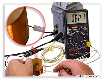
If no external changes, such as destruction of the corrugation or diffuser, are detected, but extraneous sounds appear in the form of crackling or periodic loss of sound occurs, then you should first check the flexible leads.

To do this, connect a dial ohmmeter to the speaker terminals and move the pigtails while the diffuser is stationary. If the ohmmeter needle moves, it means the flexible lead is damaged.
Other electrical defects include coil breakage and short-circuiting of part of the coil turns or the entire coil. These defects can also be detected using an ohmmeter.
| Get the Flash Player to see this player. | ||
To do this, a master oscillator signal is supplied to the amplifier input.
A partially peeled off coil or part of the turns can be identified by smoothly changing the frequency of the generator or turning on the generator in the GKCh (Swinging Frequency Generator) mode.
When testing this speaker, the frequency range 20Hz...2kHz with a period of 3 seconds was used. In this speaker, apparently, a significant part of the coil has come unstuck, as overtones are heard over a wide frequency range. If a small fragment of the coil peels off from the sleeve, overtones can appear only at a certain frequency, and only when the damaged structural element enters resonance.

In some cases, to identify a malfunction, it is useful to use an infra-low frequency generator. This can help identify, for example, defects in the gluing of the rubber corrugation to the diffuser. The arrow shows the place where the oversound is formed.
| Get the Flash Player to see this player. | ||
Rubbing the sleeve against the core or the coil against inner surface The upper flange can also be bent at a frequency of several hertz if you lightly press the corrugation waves with your fingers.
More serious damage to the speakers is even easier to detect.
So, for example, if something is heard when turning the speaker over, it means that part of the turns or the entire coil has fallen off the sleeve.
If the diffuser moves very poorly, then most likely the coil has fallen off and jammed the sleeve in the magnetic gap.
If the diffuser does not move at all, then the core may have moved and jammed the coil along with the sleeve.
Never attempt to disassemble such a speaker without first removing the sleeve, as this may also damage the cone.
How to replace speaker flex leads?
Use extreme caution when replacing flexible leads on an unassembled speaker, as a steel tool attracted by the magnetic system may damage the cone and dust cap.

If access to the flexible terminals (pigtails) of the speaker is free, then you can try to replace them without disassembling the speaker. But, in some cases, the speaker will still have to be disassembled. The picture shows a broken flexible lead.
Old flexible leads should be removed with the utmost care so as not to damage the diffuser or break the coil leads.

First, unbend the brass bracket that holds the flexible terminal, if there is one, of course.

Then the soldering area is heated with a soldering iron to separate both the flexible lead and the coil lead from the diffuser. Usually, after warming up, the glue softens and the leads can be removed.
How can I replace damaged flexible leads?
Of course, the simplest solution is to borrow flexible leads from another speaker of similar power or order from suppliers that sell spare parts for speakers. But, if this is not possible, or you want to save on spare parts, then you can make surrogate braids yourself.

The first and simpler option is to replace the failed pigtail with a piece of MGTF wire of a suitable cross-section. I don’t know who first came up with this, but it was with these flexible terminals that the once popular 4A32 speakers went on sale.

Another option is to make braids from a Soviet-made flexible telephone cable. It can still be found among all the junk at flea markets.

I am familiar with two types of such cable. In one, each wire consists of seven cores, and in the other of fourteen. Each core is made by winding copper tape onto a Mylar thread. In cross-section, the tape has the shape of a rectangle with dimensions of 0.03 x 0.3 mm.
0,03 * 0,3 * 14 = 0,126 (mm²)
As you can see, the cross-section is small, so for powerful speakers you can twist two or more stranded wires.

First, a section or sections of telephone cable are prepared using a soldering iron.

The insulation is removed in small sections to avoid damage to the cores.

Then the cores of each stranded wire are untwisted and twisted again into one wire.


And finally, the flexible lead is carefully glued twice with rubber or 88 glue with an interval of 20 minutes.
Before the first gluing, the twist must be free so that the glue penetrates between the cores. Immediately after the first gluing, the strands are twisted to the end. The second gluing finally fixes the cores relative to each other.
Thus, it is possible to make a flexible lead for a speaker of any power.

If there is no telephone or MGTF wire, then as a temporary measure you can use MGShV wire or even a braid from a shielded wire, but such pigtails do not last long, and they put a greater load on the diffuser due to less flexibility.

When installing a flexible output, you need to take into account that the weakest points of this unit are the places where the pigtail is attached to the diffuser and terminal.
If the fastening brackets are damaged or lost, the braid is secured with two crossed stitches of thread. Then the attachment point is glued with glue with a large dry residue. Weathered BF-2/BF-4 will do.
To prevent premature fracture of the pigtail, the attachment points are covered with several layers of rubber or 88 glue with a transition to a flexible terminal.
How to wind a speaker coil?
The speaker coils are wound turn by turn until the specified coil length is obtained. In this case, as a rule, the number of turns is not counted.

- Coil.
- Sleeve.
- Pad.
- Sample.
When winding, maintain constant tension on the wire and carefully lay out the turns. The turns of the second layer are laid out especially carefully, when each turn must be strictly laid between the turns of the first layer.
To make it convenient to carry out such precise work, take care of the hand rest.
The coil with winding wire can be secured in any way convenient for you and installed on the floor.
More about it a simple machine for winding speakers you can read.

Another useful tool, which will be needed for winding the coils, is this kind of clothespin with a weight.
The required viscosity of the glue can be achieved by adding a small amount of alcohol with thorough mixing.
Expand the player to full screen to see the video in full resolution.
Before the main winding, several extra turns are wound onto the sleeve in order to securely fasten the wire and sleeve to the surface of the template. Then, during the next extra turn, an even layer of glue is applied to the sleeve with a brush.
After this, the first layer of the coil is wound quickly. Then a weight is attached to the wire, which allows you to maintain the necessary tension on the wire and free up your previously occupied hand. Then, the first layer of the coil is covered with glue.
At this stage, do not try to secure the end of the wire by winding it around some object!
Any excess bend in the wire can increase the size of the coil, thereby reducing the external air gap.
If you still cannot avoid kinks in the wire, then pull it several times. problem area through the thumbnail.
After fifteen to twenty minutes, when the glue has dried, you can begin winding the second layer.
First, one or two turns of the second layer are wound, and then the first layer of the coil is covered with glue. This is done so that the fresh glue does not dissolve the glue applied earlier, and the first turn of the second layer does not fall into the gap formed between the outer turns of the first layer.
After winding the second layer of wire, the coil is dried for 10-15 minutes and then covered with glue again.
When the glue dries well, you can either remove the coil from the mandrel along with the sleeve, if it is already glued into the diffuser, or glue it into the diffuser directly on the template.
However, in some cases, the sleeve is glued into the diffuser already during speaker assembly.
To remove the sleeve from the template, the place of the gasket where the fixing drop of glue was applied is cut off, and the sleeve is removed from the mandrel along with the spool and gasket.
If the gasket does not slide along the mandrel, it means that the wire tension during winding was too high. It should be noted that excessive wire tension can reduce the gap between the sleeve and the core and make speaker assembly impossible. This is because copper wire can stretch and contract like any other metal.

Since there is a gap in the sleeve, when winding the coil, glue penetrates into it and the sleeve is glued to the gasket.
In order to separate the gasket from the sleeve, it is enough to use a brush to lightly moisten the place where the gasket is stuck to the sleeve with acetone or alcohol.
Now our coil is ready. Now it should be completely dried.
For final curing of the glue, the reel is fed electricity. The current strength is selected to achieve the optimal curing mode.
The temperature during the drying process can be measured with an electronic thermometer.
If not suitable block power supply, then the coil can be connected to the ULF and a signal from the Low Frequency Generator (LFO) can be applied to its input. The link to the software LFO is in the “Additional Materials”.
Curing mode for adhesives “BF-2”, “BF-4”.
Leave for 60 minutes. at room temperature.
Then 15 min. at 55... 60ºС.
Then 60 min. at 85... 90ºС.
Detailed description diagnostics and repair of medium and high power speakers. The article was written for those who want to repair speakers and have winding and soldering skills.
I have been repairing speakers for 15 years and want to pass on the acquired skills and techniques to the Datagorians.
Sorry for the lack of detailed photos of the process, all the equipment and work are now a thing of the past. Has your speaker whined or stopped sounding and want to bring it back to life? First - diagnostics. We remove the speaker, disconnect the wires from the terminals, having previously marked the polarity. In the future, we adhere to this rule: everything that we disassemble, draw or photograph will help a lot.
We check the winding resistance with the device. There are three possible options here.
1) Break.
2) Nominal resistance.
3) Reduced resistance.
Now for the second check. Place the speaker on the magnet and carefully move the diffuser up and down. If you hear a rustling or creaking sound, or there is no movement, the speaker will have to be disassembled.
If there is no grinding, and the winding is broken - you need to check the conductivity of the flexible wires from the terminals to the soldering of the winding. They are made of threads intertwined with copper strands, which break down over time. They can be replaced without disassembling the speaker with M.G. wire. T.F. suitable section or braided tape to remove excess solder.
We solder the wires so that they do not stretch when the diffuser moves and do not touch it. We glue the soldering area with Moment glue.
If the speaker needs to be disassembled, disconnect the wires from the terminals, place the speaker on the magnet and use a swab soaked in acetone to soften the glue around the protective cap and remove it by prying it off with a non-sharp scalpel. Using the same method, peel off the outer edge of the diffuser and the outer edge of the centering washer. Carefully pull out the diffuser vertically upward without distortion.
I do not recommend unsticking the coil frame from the diffuser and the centering washer, so as not to disturb the alignment of the speaker.
To rewind you need to assemble a simple device, the structure of which is clear from the figure. The most difficult part is the reel mandrel. To make it you need to contact a turner. Mandrel length 100-150 mm, material – any metal.

Measure the inner diameter of the coil (x). The spool mandrel should have a diameter of x+0.5mm on one edge and x-0.5mm on the other edge.
At the larger end we drill a 3.2 mm hole and cut an M4 thread for attaching the handle.
Drilling through hole 6.5 mm for stud. The surface of the mandrel must be sanded.
Now you can start winding. We will need alcohol-based glue, for example, BF-2 or BF-6, paper from the MBM capacitor, wire and a lot of patience.
We dilute the glue with alcohol. We pierce the centering washer with a needle, thread the winding wire and solder it to the flexible wire. We fix the wire at the soldering point and at the beginning of the winding, gluing pieces of paper.
If the coil frame is made of metal, we paste it with a layer of capacitor paper without overlapping layers. We wind the wire turn to turn, gluing it before winding and over it. Remove excess glue with your finger. We try to wind it not tightly, but tightly.
On the first layer we glue the paper from the capacitor without overlapping layers and perform the same steps in reverse order. When the winding is ready and soldered to the terminals, you need to connect them to a 4-5 Volt power source with a current of 1-2 Amps for drying. The winding will heat up to 50-60 degrees, while the glue will dry and harden, the coil will expand slightly. This will help you easily remove it from the mandrel.
We check the free movement of the coil in the speaker gap and begin assembly.
We need to align the coil exactly in the center. There are 2 ways to do this.
1) Place a spacer made of photographic film or x-ray film into the gap.
2) Apply a small constant voltage of 2-3 Volts to the coil so that it is pulled inward a little.
Apply a layer of Moment glue to the outer edge of the diffuser and the outer edge of the centering washer and lower the diffuser vertically down without distortion and without radial displacement, and press it. You can turn the speaker over onto a flat table, and while the glue dries, solder the wires to the terminals.
After the glue has dried, remove the gasket and check the free movement of the coil in the speaker gap.
If everything is in order, glue the protective cap in place and enjoy the result!
Thank you for your attention!
Prepared subwoofer
How to repair a car subwoofer, and subwoofers in general, is one of the frequently asked questions due to their widespread use in audio equipment.
There are three options: buy a new one, take it to a service center for repairs, or repair it yourself. To repair subwoofers yourself, you need to understand at least a little about electronics, as well as be able to use a soldering iron and a tester.
Device and troubleshooting
Subwoofer 5, 1 consists of a speaker, speaker, and amplifier, as well as a power supply:
- As a rule, it fails only from mechanical damage
- Failure of the dynamic head is caused by the contact of its coil with an audio frequency with a power for which the head is not designed, or with constant voltage, which causes the coil to burn out
- When listening to a speaker with amplification at maximum power, you will encounter the problem of wear (rupture) of the driver cone
- If the speaker breaks, it must be replaced, since rewinding the coil or repairing the subwoofer diffuser is a delicate task. painstaking work and it’s very difficult to do it efficiently so that the sound doesn’t deteriorate
First you need to find out which element of the subwoofer failed:
- A common cause of power supply failure is impaired heat exchange.
- The huge amount of dust that gradually accumulates inside the unit causes the parts to overheat and cause them to fail.
- Using a tester, we check whether there is voltage at the output of the power supply; if there is no voltage, then you can be sure that the reason lies therein
- When inspecting the parts of the power supply, you may find swollen capacitors or blackened transformer windings
- Using a soldering iron, unsolder damaged parts and replace them with new ones purchased at the store.
- You can rewind a burnt-out transformer with your own hands if you already have experience in such a matter; if you have no experience, it’s better not to take it on, or practice on something you won’t mind
- If there is voltage at the output of the power supply and it does not deviate from the specified norm, then you can move on to the low-frequency amplifier
- A board with an amplifier is a place where, as a rule, there are a lot of transistors and microcircuits. Using a tester, carefully touch the outputs of the microcircuits, measure the voltage
- When they are cold at normal supply voltage, there is probably no current in them, it should warm them up
- If the chips are hot on the contrary (they are usually slightly warm during normal operation), this is a sign of a malfunction
- Using the same analogy, we check all capacitors, swelling, hot surfaces are symptoms of their unstable operation
- The diffuser can be sealed with a back strip of tape, (preferably thin cardboard), the edges of the glued material must be thoroughly coated rubber glue so that the glue protrudes on the surface of the diffuser, the repair of the subwoofer suspension (see) is now complete
- Dry it for a day, then check the operation at low and medium power; if the sound is bad, it’s easier to replace the entire speaker than to bother with replacing the diffuser
- Replacement is a long, labor-intensive process that does not provide any guarantees of high-quality sound, plus - one careless movement, and the new diffuser will also be destroyed.
Let's move on to repairs
If you have firmly decided that rewinding the subwoofer speaker is not a problem for you, then prepare following materials and tools:
- Shellac (or epoxy) for coating the subwoofer windings
- Solvent
- Rubber glue
- Screwdriver
- Soldering iron
- Micrometer
- Screwdriver
Disassembly
Not everything is as simple as it seems do-it-yourself repair auto subwoofer, painstaking work:
- First we need to carefully disassemble and remove the subwoofer head, we should act slowly, sudden movements with hands are unacceptable, otherwise you can damage the coil sleeve
- In addition, you need to maintain cleanliness during the work process so that dust does not get into the magnetic system, and even more so metal shavings
- Otherwise, after spending a lot of time and effort, instead of a working subwoofer we will end up with a pile of ringing rubbish
- When you get to the sleeve itself, you should carefully unwind the old wire, while counting the number of turns in the layer and the total number in the coil
- Here, the more accurately you calculate, the better the quality of the repair in the end.
- Then you need to measure the diameter of the wire
- A micrometer is needed for this purpose.
- You can, of course, measure with a caliper, but the measurement accuracy is lower, if you don’t have such tools, you can cheat
- Wind the wire around a screwdriver or nail, very tightly, so that turn to turn, and so on for 10 - 30 turns, measure the length of the winding using a ruler
- Then you need to divide this length by the number of wound turns, and you will get the approximate diameter of the required wire (the ruler has a large error)
Getting ready to rewind
Now you need to prepare the subwoofer diffuser for rewinding:
- Using a mandrel suitable in diameter, secure its sleeve in the screwdriver
- It is necessary to very accurately adjust the mandrel and sleeve so as not to deform it during the rewinding process
- Apply epoxy or varnish to the surface of the sleeve
- Then you will need to clean the wire of the diameter we need
- Pass the wire through a cloth soaked in solvent
- After that, lubricate with epoxy or shellac
- Of course, after this, the instructions prescribe that the coating must dry
Rewind
We have the wire and sleeve ready, let's move on to rewinding:
- We immediately solder the beginning of the new winding to the second terminal, if we follow the direction of winding the wire (this way we eliminate unnecessary crossing of wires, this has a positive effect on the service life of the repaired speaker) and begin winding, photo below
- It is important to fix the tension and not forget to count the turns, because the more accurately we wind, the closer the speaker characteristics will be to the factory ones
- After each layer it is better to wrap it with varnish, after laying the winding, solder the second contact, cut off the wire
- Coat the entire coil with varnish again.
- After winding the coil, you will need to leave it for a day to dry completely.
- And if you used shellac, then the coil must be heated to 80-120 degrees (for example, in the oven)
- Shellac will not harden otherwise.
- This is the main inconvenience when using shellac
- But when it dries, a certain amount of elasticity remains, which completely eliminates damage to the winding from drying out of the impregnation or due to its thermal expansion
- After drying, all that remains is to attach the diffuser to the speaker, and
- The repair is considered successful if everything works
Putting it all together
To prevent the coil from rubbing against the magnetic system, we need to set a uniform circular gap:
- Paper cut into strips is suitable for this purpose.
- We insert it in a circle (where possible) between the body and the coil, thereby obtaining a uniform gap
- We check for any jams or snags by moving the diffuser gently down and up with your hand.
- Then we glue the suspension of our speaker and carefully insert it into place
- Give the parts time to dry
- Then you can pull out the centering papers
- Once again you need to check for jamming
- When everything is in order, add a layer of glue
- Let's dry it and put the finished subwoofer in the car for testing.
- Don't forget to turn the volume down by half.
- Subwoofer coil rewind completed
Now a little about the electronic filling
The device is almost the same, except that the dimensions are larger, the microcircuits or capacitors may be in a different order:
- Let's take a closer look at the voltage converter, power supply and amplifier
- The ceratec subwoofer amplifier is usually two-channel, but two channels are connected to one single dynamic head
- Moreover, each channel in the amplifier amplifies a different sound frequency, low and medium, as a rule
- In addition, almost all modern amplifiers operate on a single chip from the TDA series
- To get more power at the output of the amplifier, twelve volts from the on-board network of the car is not enough; for powerful microcircuits, the supply voltage is from 40 volts
- Therefore, in the subwoofer circuit b w there is a built-in high-frequency converter that converts the voltage of 12 volts into the one required for normal operation amplifier
- In the figure, we have divided the entire circuit into three main blocks. A1 – control of the equalizer, it fails extremely rarely, you need to try to break it, we won’t devote time to it, it changes completely
- A2 is a voltage converter, and A3 is a power amplifier. Let’s take a closer look at A2 and A3
- The voltage, through the filter, comes to capacitor C1, from there it is supplied to transistor switches VT1 and VT2
- Transistor switches are controlled by a high frequency signal generated by the DD1 microcircuit
- The amplified signal from transistors VT1-VT2 comes to transformer T1, where the voltage turns from 12 Volts to 40 Volts
- Moreover, the secondary winding of the transformer consists of two windings; for rectification, a rectifier consisting of two diodes is used
- To unload these diodes, two more diodes are installed in parallel with them
- Each of the DD2 and DD3 microcircuits is powered only by its own diodes
- To smooth out high-frequency pulses, capacitors are installed, marked C2 and C3
- Converter A2 ends here, followed by power amplifier A3
- Modern amplifiers consist of a single chip
- At its input, in order to obtain normal output parameters, a signal of a certain magnitude must be present
- The designers of this subwoofer decided that not every car radio has enough power, or rather the strength of the output signal from the primary amplifier, to obtain the nominal output parameters
- Therefore, we added a transistor to amplify the signal in front of the input of the microcircuit, in the circuit DD2 and DD3
- Here is a list of the main radio components that fail most often
- It happens that for replacing one capacitor the price in the workshop will be considerable, but the work is cheap
- Therefore, it is better to check the entire scheme yourself before paying without looking
Speaker breakdowns and methods for eliminating them
|
Symptoms of malfunction |
Treatment methods |
|
1. Doesn't play at all (no sound) |
The coil is burnt out or the wire is broken. Probably due to high power overload. |
|
2.
The mobile system does not play and is destroyed |
In such cases, serious repairs are required. |
|
3. The speaker (I apologize for the precision of the wording) “farts” |
There may be several options here: |
|
4. If the speaker doesn’t “fart”, but “grinds” |
In principle, this is the same as step 3, but the effect is less pronounced |
|
5. Extraneous sounds, but not constant, but only occasionally |
Probably dirt got into the gap (sawdust, for example) |
|
6. Rattling sound, constant and throughout the entire frequency range |
Delamination of voice coil turns. |
|
7. The same rattling sound, but only at one frequency (usually from 100 Hz to 1 kHz), something like resonance |
Something came loose in the moving system. It is necessary to check the adhesive joints on the cap, on the suspension, on the centering washer. |
|
8. “Sniffling” or whistling sounds at high amplitude |
This is “noise” from air passing through the narrow gap gaps and into the holes on the diffuser, sealed with a cloth in the Riga speaker 75GDN-1. This cannot be cured, it is a design defect. |
|
9. Yes, still... If he farts, but not constantly |
The coil came unglued from the diffuser... |
Repair for a slipped coil turn.
Unsolder first flexible liner, then saturate the gasket and suspension (corrugation and lower centering washer made of fabric) of the diffuser along the diameter in the place where it is glued to the diffuser holder (siluminum or steel basket) with solvent 646-648 (the solvent sometimes does not soften the glue, you can try xylene, toluene, benzene),
and wait for the glue to soften (from 10 to 20 minutes), when you can easily move the glued surface with your finger on the corrugation and the centering washer from the silumin diffuser holder. Carefully (DO NOT TEAR IT OFF! EVERYTHING SHOULD PULL AWAY BY ITSELF, otherwise you just poured too little solvent or waited too long) remove the diffuser from the diffuser holder. Place the coils coil by coil in place and secure thin layer BF-2 glue (it is possible, but worse, to use nitro glue) in particularly powerful heads, the coil is impregnated with a thin layer of epoxy glue. Reassemble in reverse order, generously moistening all surfaces with solvent, thereby soaking old glue again, put the diffuser in place, after centering the coil in the gap, begin gluing - pressing the fabric of the centering washer and the rubber (foam rubber - depending on the design of the head) corrugation to the silumin (steel) surface of the diffuser holder in its proper place. Center using rolled up film (for powerful heads, you can use rectangular pieces of thick cardboard, evenly distributed along the diameter of the gap, long enough for them to be easily removed from the gap after assembling the head), inserted into the gap of the core and voice coil (the cap for this is taken from the diffuser first carefully peel off, pouring solvent over the adhesive seam - make sure that the solvent does not get under the cap, otherwise the voice coil frame may peel off from the throat of the diffuser (This is exactly what happened to me: approx. Serzhi). When assembling, do not forget about the presence of a flexible connection to the coil, and do not glue past the coincidence of the coil terminals with the terminals on the diffuser holder. Using the same method, glue the gasket around the perimeter of the diffuser into place on top of the corrugation.
If there is a shortage of glue applied at the factory during assembly, glue STRICTLY with nitro glue such as Moment or Phoenix (those in large tubes) during assembly. This guarantees the ability to disassemble the head again for repairs, or in case of incorrect assembly (my old glue did not want to stick - I carefully dissolved and removed it and applied a thin layer of new one).
You need to pour a lot of solvent so that it stands and flows in the adhesive joints. You can slowly pour directly from the neck of the bottle (preferably, of course, from an oil can, which is made of chemical-resistant plastic). The solvent is toxic, don't poison yourself! He strongly rushes to the toilet after inhaling it - apparently his kidneys immediately remove the poison. Work in a ventilated place!
Protect the adhesive joints of the magnetic system itself and the center of the diffuser under the cap (glued voice coil frame) from solvent penetration, otherwise the head will fall apart. constituent elements. Apply only to the perimeter of the diffuser; carefully moisten the centering washer with a generously soaked cotton swab.
The main thing is CAREFULNESS! You can ruin everything, the paper is still there, crumple the coil frame and tear and crumple the diffuser, crumple and tear the cap.
In general, VERY GENTLE AND CAREFUL!
It is never necessary to unstick the magnetic system itself and it is unacceptable - the sensitivity (recoil) of the head may drop after gluing it again. For this reason, they are not always achieved good results in the repair of heads with a unglued magnetic system. You can glue a magnet to a core, but the magnetic force in the gap may decrease.
Rewinding a burnt out voice coil.
Carefully wind the burnt coil from the frame (if it doesn’t wind well, drop a drop of solvent), to facilitate winding and prevent the frame from collapsing, make a mandrel, which is discussed below. When winding, sketch where the beginning of the old coil was and how the terminals were sealed. Count the turns of the old coil. (Or look at the information on the speakers on this site. If it is not there yet, it will be soon :)) Select the wire exactly according to the diameter (you can measure it with a micrometer, and if you don’t have one, then wind 10 turns of wire on a suitable rod, measure the width of 10 turns with a caliper, and divide by 10) and carefully, turn to turn, wind it on a mandrel tightly inserted into the coil frame. The mandrel is made from a slightly larger piece of metal pipe (it’s better not too thick - it won’t compress) with a longitudinal cut, so that when the mandrel is inserted into the frame, the pipe can be compressed, and then it will straighten out and press the frame tightly from the inside. You can make a cut in the pipe with a hacksaw. Take the pipe of such length that it is convenient to squeeze the free end when putting the frame on it. Wind the first turn according to the beginning of winding the old coil (as a rule, the first turn is located at the neck of the diffuser and is soldered directly to the contact rivet). Secure the first turn with thread, which is removed after winding. When winding, sometimes rotate the diffuser with the coil on the mandrel to prevent the frame from sticking on the mandrel. The tension during winding is not strong - otherwise you can compress the frame together with the mandrel (for this reason, it is sometimes useful to wedge a split mandrel from the inside by inserting a suitable wire into the cut or a hard object inside the pipe). When winding, you impregnate the first layer with liquid glue - an extremely thin layer. Handle the wire gently, otherwise you may tear off the varnish insulation. After winding the coil, saturate it (in a thin layer) with liquid BF-2 glue - diluted with alcohol (epoxy - diluted with nitro solvent 646-648), tin the leads with rosin and solder them to the contact rivets. When soldering, the use of acid and acid-containing fluxes is unacceptable, only rosin!
How to try to straighten a jammed cap.
Try to peel it off carefully - generously watering the gluing perimeter with nitro solvent 646-648 (or another - see above). After peeling off, lightly moisten it with water and firmly clamp it in a vice, selecting a punch and a matrix of a suitable convex shape for it. (my finger just straightened out - it was dented a little) After several days of exposure in a vice, process inner side very liquid epoxy glue diluted with nitro solvent - a very thin layer!
Wait until it sets completely (liquefied epoxy can take more than 3 days to dry), then carefully glue it in place with “MOMENT” type nitro glue - the one that comes in large tubes.
Although in theory, such a head should of course be replaced with a new one.
When pressing the cap on the tweeter or midrange, you can try to stick tape on it and quickly pull it towards you. Must straighten up.
How to remove metal filings from a magnetic gap.
Very often, when disassembling heads, a large amount of metal filings and pieces of magnet are found in their magnetic gaps. They are removed by holding a piece of adhesive tape (insulating tape) in the gap, folded in half, with the sticky layer facing out. Some experts recommend pouring rubber glue into the gap, and after it dries, pull it out of the gap along with the sawdust. I haven’t tried it myself, and I can say that this method is most likely not suitable for many gaps in which there are free cavities between the ring magnet and the core washer and the diffuser holder flange (almost all low-frequency and high-power broadband heads with a ferrite-barium ring magnet). For those heads in which there are no such cavities, and the gap is an even longitudinal slot in depth, this method is probably possible.
A little trick.
If the coil touches, sometimes this is due to the diffuser sagging downwards due to the old age of the head. Then you can try to change its position in the column - turn the bottom of the speaker up 180 degrees in the column panel. Then if the coil has not flown off, but is simply touching it due to the diffuser sagging over time, then the sagging may be compensated.
Sometimes a hitting coil can be cured by creating an opposite distortion of the diffuser using an insert into the diffuser holder (rag, foam rubber). Leave the head in this position for several weeks, and perhaps the misalignment after removing the insert will be compensated.
Unfortunately, these tricks rarely help, and you have to disassemble the head.
The principle of the electrodynamic GG device is shown in Fig. 1.

Fig 1. The device of the electrodynamic head of the loudspeaker / - diffuser holder, 2 - movable system 1, 3-magnetic circuit
The loudspeaker head consists of three main parts - a magnetic circuit 3, a moving system 2 and a diffuser holder 1.
The magnetic circuit of the GG can be made in two versions: shielded or unshielded, depending on the requirements for the equipment in which the GG is used. Various options shielded core, ring with cast magnets and ring with additional shield and unshielded circuits are shown in Fig. 2.

Fig 2. Design of the magnetic circuit of the loudspeaker head a - shielded circuit with a core magnet, b - unshielded circuit with a ring magnet, c - circuit with a ring magnet and an external screen, 1 - core, 2 - upper flange, 3 - permanent magnet, 4 - lower flange ( or glass), 5 - screen, 6 - tip
The magnetic circuit of the GG consists of elements of the magnetic circuit of the upper flange 2, cup 4, core 1 and permanent magnet 3 with tip 6 (Fig. 2.a) or the upper and lower flanges 2 and 4, core 1 and permanent magnet 3 (Fig. 2 , b). Sometimes it is placed in a shielding glass (Fig. 2, c). The constant magnetic flux created by the magnet using magnetic flanges and the core is directed into the air working gap, which has the form of an annular cylindrical slot between the core and the upper flange
Ring ferrite-barium magnets (25BA170, 28RA180) are usually used as permanent magnets in unshielded circuits; in shielded ones, cast cobalt-containing (YN13DK24) or rare-earth magnets are used. For the manufacture of magnetic circuit parts, mild electrical or structural steel is usually used (Art. 10)
The efficiency of the GG as an electromechanical transducer is characterized by the product of the magnetic field induction in the gap and the length of the conductor (i.e., the length of the voice coil wire). The magnitude of the induction and the structure of the magnetic field distribution are affected by the width and height of the working gap, the configuration of the flanges and core, as well as the volume and width of permanent magnet.

Fig 3. Design of the moving head system
loudspeaker a - with a conical diffuser, b - with a dome diaphragm,
1 - voice coil 2 - centering washer, 3 - flexible leads, 4 -
suspension, 5 - diffuser (diaphragm), 6 - dust cap
Figure 3 shows the mobile GG system. It includes suspension 4, cone diffuser or dome diaphragm 5, centering washer 2, dust cap 6, voice coil 1, flexible leads 3.
Suspension 4 has the form of a corrugated annular shell, which has great flexibility in the axial direction, which allows the diffuser to perform axial vibrations with a large displacement amplitude. The suspension is cast together with the diaphragm from paper pulp or made from special soft materials(rubber, polyurethane foam, etc.)
The diaphragm (diffuser) 5 is an elastic shell of rotation (conical, dome or flat), which oscillates under the action of an axial mechanical force from the coil, exciting vibrations in the air environment and emitting sound. Currently, most GGs use diffusers made of natural cellulose materials with a successful combination physical and mechanical parameters. IN last years Polymer, honeycomb, metal and composite materials are used as materials for diaphragms (diffusers).
Centering washer 2 is a corrugated membrane that ensures centering of the voice coil in the gap, prevents the occurrence of circular vibrations, allowing the diaphragm to make large displacements in the axial direction. Centering washers are usually made of cotton fabric, cambric or chiffon, impregnated with bakelite varnish.
Dust cap 6 is a dome or flat membrane that protects the gap from dust, acting as an additional stiffener on the diaphragm. It is usually made from paper pulp, fabric or metal foil.
Voice coil 1 is a cylindrical frame with an insulated conductor wound in several layers. As a rule, the number of layers of the voice coil is even, so that its leads come out in one direction. When an alternating current magnetic circuit flows through a voice coil placed in a radial cylindrical gap, it will be affected by mechanical force, under the influence of which vibrations of the voice coil and the associated diaphragm occur. The coil frame is usually made of cable paper or metal foil; copper or aluminum wire in enamel insulation is used as a conductor.
Flexible leads 3 connect the voice coil conductor to the output connecting terminals GG.
The diffuser holder serves to connect the magnetic circuit, the moving GG system and provides fastening in the housing of the equipment where it is used. The diffuser holder is usually made by stamping from steel or by casting from silumin.
All elements of the moving system and magnetic circuit have a significant impact on the electroacoustic characteristics and sound quality of the GG.
Disassembling and assembling the speaker
First, the patient's flexible lead wires were unsoldered (from the side of the contact pads)
 |
Then, with a solvent (646 or any other capable of dissolving glue, such as “Moment”), using a syringe with a needle, the place where the dust cap and diffuser were glued together (around the perimeter) was moistened... |
 |
Place where the centering washer is glued to the diffuser (along the perimeter)... |
 |
And the place where the diffuser itself is glued to the diffuser holder basket (again around the perimeter) The speaker was left in this state for about 15 minutes with periodic repetition of the previous three steps (as the solvent was absorbed/evaporated) |
|
Attention! When working with solvent, you should observe safety precautions - avoid contact with skin (work with rubber gloves!) and mucous membranes! Don't eat or smoke! Work in a well-ventilated area! When wet - use a small amount solvent, avoiding getting it into the place where the coil and centering washer are glued! |
|
 |
Depending on the type of solvent and air temperature, after 10-15 minutes of the above operations, using a sharp object, you can carefully pry up the dust cap and remove it. The cap should either come off very easily or offer very little resistance. If you need to apply significant force, repeat the operation by wetting its edges with solvent and waiting! |
 |
After peeling off the cap, carefully pour out the remaining solvent from the recess near the coil mandrel (by turning the patient over). |
 |
By this time the centering washer has time to come off. Carefully, without any effort, separate it from the diffuser holder basket. if necessary, re-wet the gluing area with solvent. |
 |
We wet the place where the diffuser is glued to the diffuser holder. We wait... We wet it again and wait again... After 10 minutes you can try to peel off the diffuser. Ideally, it should effortlessly separate from the diffuser holder (along with the coil and centering washer). But sometimes he needs a little help (the main thing is to be careful! Do not damage the rubber suspension!!!) |
 |
We clean the gluing areas from old glue and dry the disassembled speaker. |
 |
We examine the disassembled patient to determine if there is a malfunction. Let's look at the reel. If there are no abrasions or loose threads on it, we leave it alone. When a thread comes off, glue it back with a thin layer of BF-2 glue. |
 |
We carefully inspect the place where the supply wires are attached to the diffuser. So it is - the patient has the most common malfunction found in old speakers with a large diffuser stroke. The supply wire at the attachment point is frayed/broken. What kind of contact can we talk about when everything hangs on a thread running through the center! Carefully bend the copper “tendrils”... And unsolder the supply wire. We cut off the supply wires at the break point... |
 |
And we tin the resulting ends (of course, we first use rosin). Care is required here! Use a small amount of low-melting solder - the solder is absorbed into the wiring like a sponge! Carefully solder the wiring into place, bend the copper “tendrils” and glue it with glue (Moment, BF-2) where the wiring connects to the diffuser. Let us remember - you cannot solder wires to the fastening “antennae”! Otherwise, how can the wiring be changed again in ten years? ;), |
 |
Assembling the speaker. We place the diffuser with all the “equipment” in the diffuser holder, orienting the wiring to the places where they are attached. Then we check the correct polarity - when connecting a 1.5V AA battery to the terminals, when connecting the “+” battery to the “+” speaker, the diffuser will “jump” out of the basket. We place the diffuser so that its “+” supply wire is at the “+” mark on the speaker basket. |
 |
We solder the lead wires to the contact pads. Please note that the length of the wires has decreased by almost half a centimeter. Therefore, we solder them not as it was at the factory - to the hole in the plate, but with a minimum margin, to preserve the length. |
 |
We center the diffuser in its basket using photographic film (or thick paper), which we place in the gap between the core and the coil. The main rule is to place the centering evenly around the perimeter to maintain the same gap. The amount (or thickness) of centering should be such that when the diffuser is slightly protruded outward, it will freely rest on it and not fall inward. For the 25GDN-1-4 speaker, 4 pieces of photographic film, placed in pairs in front of each other, are enough for this. The length of the photographic film should be such that it does not interfere if you place the speaker on the diffuser. For what - read below. |
|
Glue the diffuser. We use the indication for the glue used (I recommend “Moment”, main criterion choice so that the glue can later be dissolved with a solvent). I usually stick the diffuser 1-1.5 cm up so that the centering washer does not touch the diffuser holder basket, then I apply a thin layer of glue to it and the basket with a brush, wait and firmly push the diffuser inside, additionally pressing the washer to the basket around the perimeter using my fingers . Then I glue the diffuser (in the retracted state, avoiding distortion). We leave the speaker upside down for several hours under a load (this is why our photographic film should not protrude beyond the plane of the diffuser!)... |
|
|
Then we check the speaker for correct assembly. We take out the centering and carefully check the movement of the diffuser with our fingers. It should walk easily, without making overtones (there should be no touching of the coil and the core!). We connect the speaker to the amplifier and feed it low-frequency tones at a low volume. There should be no extraneous sounds. If the gluing is incorrect (misalignment, etc.), the speaker must be unstuck (see above) and reassembled, being careful! With high-quality assembly, 99% of the time we will get a fully working speaker. |
|
 |
We coat the edge of the dust cap with glue, wait and carefully glue it to the diffuser. Care and precision are required here - a crookedly glued cap does not affect the sound quality, but it greatly spoils appearance dynamics. When gluing, do not press on the center of the cap!!! This may cause it to bend and you will have to peel it off, straighten it, coat the inside with a thin layer of epoxy for strength and glue it back. |
 |
We wait until all the parts are completely glued together (about a day) and put the finished speaker in its place. We enjoy the sound, which is no worse than that of a new factory similar speaker. |
That's it, now you see that fixing the speaker is an easy task. The main thing is slowness and accuracy! So, in an hour, you can leisurely repair almost any woofer or midrange speaker, domestic or imported (for gluing up imported speakers, a more powerful solvent is often required, such as acetone or toluene, be careful - they are poisonous!!!) that has a similar defect.
Yes, after the operation, the former patient got his second wind and the cheerful yellow subs continue to do their hard bass work.