Let's begin!
What will we collect from?
We need to choose the heart of our system. In my opinion, for such signaling there is nothing better than Arduino Uno. The main criterion is a sufficient number of “pins” and price.
Key Features of Arduino Uno
Microcontroller - ATmega328
Operating voltage - 5 V
Input voltage (recommended) - 7-12 V
Input voltage (limit) - 6-20 V
Digital Inputs/Outputs - 14 (6 of which can be used as PWM outputs)
Analog inputs - 6
Constant current through input/output - 40 mA
Constant current for output 3.3V - 50mA
Flash memory - 32 KB (ATmega328) of which 0.5 KB is used for the bootloader
RAM - 2 KB (ATmega328)
EEPROM - 1 KB (ATmega328)
Clock frequency - 16 MHz
Fits!
Now you need to select a GSM module, because our alarm system must be able to notify the car owner. So, you need to google it... Here, an excellent sensor - SIM800L, the size is simply wonderful.

I thought and ordered it from China. However, everything turned out to be not so rosy. The sensor simply refused to register the SIM card on the network. Everything possible was tried - the result was zero.
Found good people who provided me with more cool thing- Sim900 Shield. Now this is a serious thing. The Shield has both a microphone and headphone jack, making it a full-fledged phone.

Key Features of Sim900 Shield
4 operating frequency standards 850/ 900/ 1800/ 1900 MHz
GPRS multi-slot class 10/8
GPRS mobile station class B
Complies with GSM phase 2/2+
Class 4 (2 W @850/ 900 MHz)
Class 1 (1 W @ 1800/1900MHz)
Control using AT commands (GSM 07.07, 07.05 and SIMCOM extended AT commands)
Low power consumption: 1.5mA(sleep mode)
Operating temperature range: -40°C to +85°C
Fits!
Ok, but you need to take readings from some sensors in order to notify the owner. If the car is towed away, then the position of the car will obviously change in space. Let's take an accelerometer and a gyroscope. Great. Ok, now we are looking for a sensor.
I think that the GY-521 MPU6050 will definitely fit. It turned out that it also has a temperature sensor. We should use it too, there will be such a “killer feature”. Let's assume that the owner of the car parked it under his house and left. The temperature inside the car will change “smoothly”. What happens if an intruder tries to break into the car? For example, he will be able to open the door. The temperature in the car will begin to change rapidly as the air in the cabin begins to mix with the air environment. I think it will work.

Main Features of GY-521 MPU6050
3-axis gyroscope + 3-axis accelerometer GY-521 module on MPU-6050 chip. Allows you to determine the position and movement of an object in space, angular velocity during rotation. It also has a built-in temperature sensor. It is used in various copters and aircraft models; a motion capture system can also be assembled based on these sensors.
Chip - MPU-6050
Supply voltage - from 3.5V to 6V (DC);
Gyro Range - ±250 500 1000 2000°/s
Accelerometer range - ±2±4±8±16g
Communication interface - I2C
Size - 15x20 mm.
Weight - 5 g
Fits!
A vibration sensor will also come in handy. Suddenly they try to open the car with “brute force”, or in the parking lot another car hits your car. Let's take the vibration sensor SW-420 (adjustable).

Main characteristics of SW-420
Supply voltage - 3.3 - 5V
Output signal - digital High/Low (normally closed)
Sensor used - SW-420
The comparator used is LM393
Dimensions - 32x14 mm
Additionally - There is an adjustment resistor.
Fits!
Screw on the SD memory card module. We will also write a log file.

Main characteristics of the SD memory card module
The module allows you to store, read and write to an SD card the data required for the operation of a device based on a microcontroller. The use of the device is relevant when storing files from tens of megabytes to two gigabytes. The board contains an SD card container, a card power stabilizer, and a connector plug for interface and power lines. If you need to work with audio, video or other large-scale data, for example, keep a log of events, sensor data or store web server information, then the SD memory card module for Arduino will make it possible to use an SD card for these purposes. Using the module, you can study the features of the SD card.
Supply voltage - 5 or 3.3 V
SD card memory capacity - up to 2 GB
Dimensions - 46 x 30 mm
Fits!
And let's add a servo drive; when the sensors are triggered, the servo drive with the video recorder will turn and shoot a video of the incident. Let's take the MG996R servo drive.

Main Features of MG996R Servo Drive
Stable and reliable protection from damage
- Metal drive
- Double row ball bearing
- Wire length 300 mm
- Dimensions 40x19x43mm
- Weight 55 g
- Rotation angle: 120 degrees.
- Operating speed: 0.17sec/60 degrees (4.8V no load)
- Operating speed: 0.13sec/60 degrees (6V no load)
- Starting torque: 9.4kg/cm at 4.8V power supply
- Starting torque: 11kg/cm at 6V power supply
- Operating voltage: 4.8 - 7.2V
- All drive parts are made of metal
Fits!
We collect
There are a huge number of articles on Google about connecting each sensor. And I have no desire to invent new bicycles, so I will leave links to simple and working options.Spring, as you know, is accompanied by all sorts of aggravations, and now the main “exacerbation” has crawled out of its holes onto the street in order to appropriate for itself what does not belong to it. This means that the topic of protecting your property is becoming more relevant than ever.
The site already has several reviews of homemade ones. They are of course functional, but everyone has general feature- dependence on the outlet. If this is not a problem with a property where electricity is already supplied, then what about a property where the outlet is far away or the surrounding area is completely de-energized? I decided to take a different route - to assemble a long-lived device that is as simple as possible and independent of mains power, which will sleep all the time, and when robbers break in, it will start up and call the owner’s phone, signaling with a simple alarm call.
Review Items
Purchased:1. Bread board single sided 5x7 cm: getinaks- or fiberglass
* - fiberglass is much better quality than getinax.
2. Neoway M590 module - with antenna on PCB -
3. Arduino Pro Mini "RobotDyn" ATmega168PA 8MHz 3.3V -
4. Lithium charge-discharge control board -
Mined from the ruins of civilization:
1.
Racks for boards, cut from device housings - 6 pcs.
2.
Lithium flat battery 1300mAh
3.
Staples used to secure the cable to the wall
4.
Stationery eraser
5.
Copper wire 1.5mm thick
6.
Instrument housing from the local radio market - 1.5$
7.
Pair of LEDs different color(taken from VHS player)
8.
Antenna and button with cap (taken from Wi-Fi router)
9.
4-pin terminal block (taken from dimmer)
10.
Power connector (taken from an old charger for 18650)
11.
6-pin connector (taken from DVD drive)
12.
Tin can (coffee can, for example)
Arduino Pro Mini "RobotDyn" Atmega 168PA 3.3V 8MHz
Specifications:Microcontroller: ATmega168PA
Direct operating voltage:.8 - 5.5 V
Operating voltage through stabilizer LE33: 3.3 V or 5 V (depending on model)
Working temperature:-40°C… 105°C
Input voltage: 3.35-12V (3.3V model) or 5-12V (5V model)
Digital Inputs/Outputs: 14 (6 of which can be used as PWM outputs: 3, 5, 6, 9, 10, and 11)
Analog inputs: 6
Timers-counters: two 8-bit and one 16-bit
Energy Saving Modes: 6
DC current via input/output: 40 mA
Flash memory: 16 KB (2 used for bootloader)
RAM: 1 KB
EEPROM: 512 bytes
Memory recording/erasing resource: 10,000 Flash/100,000 EEPROM
Clock frequency: 8 MHz (3.3 V model) or 16 MHz (5 V model)
SPI: 10 (SS), 11 (MOSI), 12 (MISO), 13 (SCK)
I2C: A4 (SDA) and A5 (SCL)
UART TTL: 0 (RX) and 1 (TX)
Datasheet:
The choice fell on this atmega completely by accident. On one forum where energy-efficient projects were discussed, in the comments there was advice to use the 168th atmega.
However, I had to tinker to find such a board, since quite often all the lots were filled with 328 atmegs at a frequency of 16 MHz, operating from 5V. For my project, such characteristics were redundant and inconvenient from the very beginning, and the search became more complicated.
As a result, I came across a 3.3-volt version of Pro Mini on Atmega 168PA on eBay, and not just a simple Chinese one, but under the RobotDyn brand from a Russian developer. Yes, at first, like you, I also had a grain of doubt. But in vain. When the project was already assembled, and AliExpress introduced mandatory paid delivery for cheap goods (after which parcels began to get lost much more often), I later ordered a regular Pro Mini Atmega168 (without PA) 3.3V 8MHz. I experimented a little with power saving modes with both boards, flashing a special sketch into each that put the microcontroller into maximum power saving mode and this is what came out:
1) Arduino Pro Mini "RobotDyn": ~250µA
2) Arduino Pro Mini “NoName”: when power is supplied to the voltage stabilizer (RAW pin) and the LED is soldered, the current consumption is ~3.92mA

- as you understand, the difference in energy consumption is almost 16 times, all because NoName's Pro Mini uses an Atmega168+ combination, of which the MK itself eats only 20uA current (I checked this separately), all the rest of the gluttony is accounted for by the AMS1117 linear voltage converter - the datasheet only confirms this: 
In the case of the board from RobotDyn, the combination is somewhat different - this is the Atmega168PA+ - here a different LDO stabilizer is used, whose characteristics in terms of energy saving turned out to be more pleasant: 
I didn’t desolder it, so I can’t say how much current the Atmega168PA consumes pure form. IN in this case I had enough ~250µA when powered by Nokia lithium battery. However, if you unsolder the AMS1117 from the NoName" motherboard, then the regular ATmega168, in its pure form, as I said above, consumes 20uA.
LEDs with power supply can be knocked off with something sharp. It's not a problem. The stabilizer was desoldered with a hairdryer. However, not everyone has a hair dryer and the skills to work with it, so both of the above options have a right to exist.
Neoway M590E module
Specifications:Frequencies: EGSM900/DCS1800 Dual-band, or GSM850/1900 or Quad-band
Sensitivity:-107dBm
Maximum transmit power: EGSM900 Class4(2W), DCS1800 Class1(1W)
Peak current: 2A
Working current: 210mA
Sleep current: 2.5mA
Working temperature:-40°C… +85°C
Operating voltage: 3.3V…4.5V (recommended 3.9V)
Protocols: GSM/GPRS Phase2/2+, TCP/IP, FTP, UDP etc.
Internet: GPRS CLASS 10
Datasheet:
The cheapest GSM module that can be found on the market, usually used, soldered not always by skillful with Chinese hands from equipment. Why not always dexterous? Yes, all because of desoldering with a hairdryer - often people receive these modules with shorted plus and minus, which is one of the reasons for their inoperability. Therefore, the first step is to check the power contacts for a short circuit.
Note. I would like to note a separate important point, in my opinion, that these modules can come with a round coaxial connector for the antenna, which allows you to separately order a more serious antenna and connect it to the module without dancing with a tambourine. Or they may come without this connector. This is if we talk about the cheapest sets. If you don’t want to rely on a happy accident, then there are slightly more expensive sets where this connector is present + the kit includes an external antenna on a textolite board.
This module is also capricious when it comes to power supply, since at peak it consumes up to 2A current, and the diode included in the kit seems to be designed to lower the voltage from 5V (which is why it says 5V on the board itself) to 4.2V, but judging by According to people's complaints, it creates more trouble than it is worth.
Let's say you have already assembled this module, and instead of a diode, a jumper is soldered in, since we are not going to supply a voltage of 5V to it, but will power it directly from a lithium battery, which is within the permissible voltage limits of 3.3-4.2V.
It will be necessary to somehow connect it to the computer and check for functionality. For this case, it is better to buy one for yourself in advance - through it we will communicate with the module and Arduino boards via the UART serial interface (USART).
The connection is shown below in the picture (I drew it as best I can):
TX modem >>> RX converter
RX modem<<< TX конвертера
Battery plus - Modem plus
The negative of the lithium battery is combined with the GND of the modem and the GND of the converter
To start the modem, apply the BOOT pin through a 4.7 kOhm resistor to GND

In the meantime, run the program on your computer. Pay attention to the settings:
1) Select the COM port to which the TTL converter is connected, in my case it is COM4, yours may be different.
2) Select the data transfer speed. (There is a nuance here, because the modules themselves can be configured for different speeds, most often 9600 baud or 115200 baud. Here you need to select it empirically, choosing some speed, connecting, and sending the AT command, if the cracks come in response, then it will disconnect , select a different speed and repeat the command, and so on until the answer is OK).
3) Select the packet length (in this case 8 bits), parity bit disabled (none), stop bit (1).
4) Be sure to check the box +CR, and then a carriage return character will be automatically added to each command we send to the module at the end - the module understands commands only with this character at the end.
5) Connection, everything is clear here, click and we can work with the module.

If you click on “Connection” and then start the module by applying BOOT through a 4.7K resistor to ground, then first the terminal will display the inscription “MODEM:STARTUP”, then, after a while, the inscription “+PBREADY”, meaning that the telephone number has been read book, even though it may be empty: 
Under this spoiler are AT commands with examples
We print the AT command - in response, the module sends us our command, since the echo mode is enabled, and OK: 
Let's check the status of the modem with the AT+CPAS command - the response is again our command, +CPAS: 0 and OK.
0 means that the module is ready for operation, but depending on the situation there may be other numbers, for example 3 – incoming call, 4 – in connection mode, 5 – sleep mode. I couldn’t find any information on 1 and 2. 
Changing the data transfer rate via UART is done with the command AT+IPR=9600 - this is if you need a speed of 9600. If something else, similar to AT+IPR=19200, for example, or AT+IPR=115200. 
Let's check the network signal. AT+CSQ, the response comes +CSQ: 22.1 - the value before the decimal point has a range of 0... 31 (115... 52 dBl) - this is the signal level, the higher the better. But 99 means its absence. The value after the decimal point is the signal quality 0... 7 - here it’s the other way around, the lower the number, the better. 
Let's disable echo mode by sending the ATE0 command so that duplicate commands do not interfere. This mode is switched back on using the ATE1 command. 
View firmware version AT+GETVERS 
These and many other commands can be viewed
Aligning boards
If soldering the Pro Mini to a breadboard is not difficult, then with the GSM module the situation is somewhat more complicated, because its contact comb is located only on one side, and if you solder only it, then the other side of the board will simply hang in the air. Then, again, I had to drill additional 3 holes by eye near the three corners on the board. The areas around each of the holes were then masked off. For convenience, I placed the disconnected leads from the comb on a solderless breadboard (white) and, installing the GSM module board on them, soldered them normally:
Later I had to make another hole, in my case on the letter “I”, where it says “Made In China”, from the edge of the board. 
It turned out that the added contact, which is essentially GND, became located next to the GND of the Pro Mini board, and thus it became possible to connect the ground of the GSM module and the Pro Mini with a drop of solder (the long pin in the middle and the Pro Mini pin to the right of it) - I marked them with arrows. Of course it turned out a little crooked, but now it holds securely: 

There was some space left between the boards - in it I placed a lithium discharge charge control board with a pre-soldered microUSB connector and soldered wires. 
The scarf fits in there very tightly, and the glow of the LEDs on the side will be clearly visible through a small hole in the case. 

Card racks
In order to securely mount the board inside the case, I had to spend a couple of days thinking about how this could be implemented. The option with hot-melt adhesive was not considered for several reasons - it could fall off, become deformed, and most importantly, the structure would be difficult to disassemble.I came to the conclusion that the simplest and most correct option here would be to use stands, which naturally I did not have. However, there were a couple of non-working chargers, from which one long stand with a thread for self-tapping screws was cut out. Each stand was sawn in half and filed down to about 9.5 mm - it is at this height that the battery located under the board has a sufficient margin of about 2 mm - this is done so that the soldered contacts of the board with their tips do not touch it and so that it is possible to put a piece between them foam for fixation.
As for attaching the board directly to the case, here I cut four strips from a coffee can, drilled a hole at the ends of which, then secured them on the same screws that are screwed into the racks. See in the photo below what it looks like.
The next step is to screw a couple of stands on the other side of the board, that is, on top, so that when the case is closed, the cover rests slightly on these stands, creating additional fixation. A little later, for this purpose, I came across a housing from a Soviet propaganda radio (if it had been found earlier, I would have taken all the stands from here), where I found a couple of more or less suitable heights, but first I drilled them in the center with a drill under self-tapping screws Then I sawed them off and also finished them off with a file, removing the excess. Here I came up with one subtlety - in the photo you can see that one white stand is screwed to the getinaks board from the edge, and the other white one is screwed directly to the module board, because from one edge the modem board completely covers the bottom board, and from the opposite edge - on the contrary - the bottom one is already peeking out. At the same time, additional holes had to be drilled in both boards so that the heads of the screws could pass freely.
And finally, it remains to make sure that the board is always parallel to the body - the staples that are used to fix wires and cables on the wall are perfect for this task; I previously removed the nails from them. The brackets cling well to the board with the concave side without any additional devices, the only thing is to the right of the SIM card, the width of the bracket turned out to be excessive and I also had to sand it.
All details were adjusted by eye and experimentally, below is a photo of all of the above:


Connectors. LEDs. Button.
Since I ran out of comb, I had to remove the 6-pin connector from the DVD drive board, which I then soldered to the Pro Mini, this is for the convenience of flashing the board. Nearby I soldered a round connector (Nokiev 3.5mm) for charging lithium.
The body of the 6-pin connector was slightly finished with a file, because its edges protruded slightly above the body. The charging socket fits perfectly against the wall of the case. 
On the other side of the board, I soldered a button to reboot the device and two LEDs for debugging the firmware - the red LED is connected to the GSM module, the second green LED is connected to the 10th pin of the Pro Mini - it’s easier for me to debug the program. 
Battery modification
The flat Nokia battery from Nokia phones is no less common than the 18650, but many simply refuse to use it due to the inconvenience of connecting the contacts, which are recessed deep into the battery itself. It is undesirable to solder them, so it was decided to use the method proposed by these, namely, make a contact block yourself from an office eraser and copper wire (1.5 mm thick).First, I pierced a piece of eraser with two wires with pre-stripped ends, and adjusted them to the battery contacts so that the distance between them coincided,
I bent the ends, tinned them with a soldering iron, and pulled them back slightly by the long ends so that the resulting contacts were recessed into the eraser.


Trying on a battery: 
You can secure the contact block with a rubber band or wrap it with blue electrical tape, which is what I did in the end. 
Assembly.
The main part of the work is done, all that remains is to assemble and record it.I put a piece of foam rubber between the battery and the board so that it would not move inside the case later. I additionally soldered a 2200 µF capacitor to power the module.

When charging is connected: 
Frame. External terminal block.
The case was available on the local radio market for about $1.5, if converted into dollars, measuring 95x60x25mm, almost the size of a pack of cigarettes. I drilled several holes in it. First for the 4-pin terminal block, taken from a non-working dimmer.I completely freed the two outer contacts from the bolts with spacers, drilled holes for longer bolts, which will hold the entire terminal block on the body. On the case itself, of course, the two outer holes will be large, and the two in the middle will be smaller - they will have contacts threaded through them, one of which is connected to VCC Pro Mini, and the second contact to pin 2.

Drilling holes, although a simple task at first glance, is still no less labor-intensive, it is very easy to miss, so I did it first with a drill of a smaller diameter, then with a larger one. 
For the tact button, I chose a cap with a slightly concave top, so that it would be easy to reach with a match or paper clip through the narrow hole in the case. 
Board in a case with a connected USB-TTL converter cable: 
About the antenna.
The antenna, as you may have noticed throughout the review, was constantly changing as I experimented with different homemade antennas. Initially, there was a round coaxial connector on the module board, but the fifth time it was used for an external antenna, it simply fell apart, so keep in mind that it is flimsy. As a result, I tore out the antenna on the PCB from the old router, and soldered it to the module board, because... it catches the net a little better than spring and wire. 
Well, completely assembled with the charging connected it looks like this: 
Test. How it works:
In addition to tests with antennas, I checked how the alarm would behave outside, in -15 frost. To do this, I simply placed the entire insides in a container and left it on the balcony overnight, the alarm did not start, the reason turned out to be generally obvious - lithium does not like frost. This was confirmed by another test, where I left the battery at home, and took the board outside through long wires and left it like that for a day in the same frost - it worked as if nothing had happened. On the other hand, it would be strange if the alarm did not work because... In the datasheets for Atmega, for modules, and for quartz, the permissible operating temperatures are up to -40 degrees.
The principle of operation is organized using an external interrupt, initially pin 2 is closed to VCC and thus logical 1 is maintained at the pin, and the controller is asleep. As soon as the contact is broken and 0 appears on pin 2, the microcontroller wakes up, lowers the 3rd pin (to which the BOOT of the modem is connected through a resistor) to ground - the module starts, the MK periodically polls the module for readiness, and as soon as it catches the network, it immediately sends call to the owner's phone number specified in the code. After rejecting the call, the device turns off without sending any more endless calls, which is the problem with many Chinese alarm systems.
Additional Information
#include
Circuit diagram (without charge-discharge control board) 
Conclusions and thoughts. Plans.
The alarm is used at the dacha, I am satisfied with the work, however, with further study of the AVR, more and more ideas come up for further modification. Arduino with its pseudo-language Wiring really upset me, because... One unpleasant moment was discovered in the work. When I used the port functions digitalWrite(); or pinMode(); - for some reason the GSM module froze very often. But it was worth replacing them with tricks like DDRB|=(1<On energy saving...
The assembled device worked for four full months without recharging and continues to work, although it would be more correct to say “sleep”. This can be checked by simply rebooting via the white button. With a power consumption of 250 μA (through the LE33 stabilizer) and a battery of ~1430 mAh, although okay, due to the newness of the battery, let’s round it up to 1000 mAh, it turns out that the device can sleep for about 5.5 months without recharging. If you still remove the stabilizer, then the operating time can be safely multiplied by 10 times. But in my case there is no need for this, because you still need to spend the balance from the SIM card once every three months, at the same time the device can be checked and recharged.
The example of energy saving given in the review is far from the limit, because judging by the information from the datasheet, you can lower the clock frequency of the microcontroller (and this is done by installing fuses) to 1 MHz and, if you apply 1.8 V voltage, the consumption will drop below the 1 μA bar in active mode. Very nice! But if the MK is clocked from the internal RC oscillator, then another problem will appear - the UART air will be clogged with garbage and errors, especially if the controller is heated or cooled.
Upon completion...
1)
An ordinary wire installed to break is not very convenient, I plan to experiment with a Hall sensor and a reed switch, although they say about the latter that it is not very reliable, because the contacts inside it can stick.
2)
It would be nice to add the ability to change the “owner number” without the participation of a computer and flashing it. You will have to work with the EEPROM.
3)
Try interruptions from the watchdog timer, but not just for the sake of curiosity, but so that the microcontroller periodically wakes up on its own, measures the battery voltage and sends the resulting value via SMS to be aware of how low the battery is.
4)
A solar panel can completely eliminate the need to recharge the device; this will be especially true for low-capacity batteries.
5)
For a long time I wanted to buy LiFePo4 batteries, which, according to reviews, can withstand frost well, but while I was looking for a suitable lot, spring had already quietly arrived.
6)
Work on the aesthetic component
Which Pro Mini should you buy?
If you don’t have a hair dryer, then Pro Mini “RobotDyn” Atmega168PA 3.3V, pick off the LED with something sharp and you have ~250 µA.
If you have a hair dryer, then any board, solder the stabilizer and the LED for power supply - you get ~20 µA of current consumption.
That's all for now, I hope the review was interesting and useful.
Planning to buy +174 Add to favorites I liked the review +143 +278Good day :) Today we’ll talk about alarms. The service market is full of companies and organizations that install and maintain security systems. These companies offer the buyer a wide selection of alarm systems. However, their cost is far from cheap. But what should a person do who doesn’t have a lot of personal funds to spend on a security alarm? I think the conclusion suggests itself - do alarm their hands. This article provides an example of how you can make your own coded security system using an Arduino uno board and several magnetic sensors.
The system can be deactivated by entering the password from the keypad and pressing the ‘ button * ‘. If you want to change the current password, you can do this by pressing the ‘ key B‘, and if you want to skip or interrupt the operation, you can do this by pressing the key ‘#’. The system has a buzzer to play various sounds when performing a particular operation.
The system is activated by pressing the ‘A’ button. The system gives 10 seconds to leave the room. After 10 seconds have passed, the alarm will be activated. The number of magnetic sensors will depend on your own desire. The project involves 3 sensors (for two windows and a door). When the window opens, the system is activated and the alarm signal coming from the buzzer is activated. The system can be deactivated by entering a password. When the door opens, the alarm gives the person entering 20 seconds to enter the password. The system uses an ultrasonic sensor that can detect movement.
Video of device operation
Craft Made for informational/educational purposes. If you want to use it at home, you will need to modify it. Enclose the control unit in a metal case and protect the power line from possible damage.
Let's begin!
Step 1: What will we need?

- Arduino uno board;
- high-contrast LCD display 16×2;
- keyboard 4x4;
- 10~20kΩ potentiometer;
- 3 magnetic sensors (aka reed switches);
- 3 2-pin screw terminals;
- HC-SR04 ultrasonic sensor;
If you want to build a system without using Arduino, you will also need the following:
- DIP connector for atmega328 + microcontroller atmega328;
- 16MHz quartz resonator;
- 2 pcs. 22pF ceramic, 2 pcs. 0.22uF electrolytic capacitor;
- 1 PC. 10kOhm resistor;
- DC power jack;
- bread board;
- 5V power supply;
And one box to pack it all in!
Tools:
- Something to cut a plastic box with;
- Hot glue gun;
- Drill/screwdriver.
Step 2: Alarm Circuit

The connection diagram is quite simple.
Small clarification:
High contrast LCD:
- Pin1 - Vdd to GND;
- Pin2 - Vss to 5V;
- Pin3 - Vo (to the central terminal of the potentiometer);
- Pin4 - RS to Arduino pin 8;
- Pin5 - RW to GND;
- Pin6 - EN to Arduino pin 7;
- Pin11 - D4 to Arduino pin 6;
- Pin12 - D5 to Arduino pin 5;
- Pin13 - D6 to Arduino pin 4;
- Pin14 - D7 to Arduino pin 3;
- Pin15 - Vee (to the right or left terminal of the potentiometer).
Keyboard 4x4:
From left to right:
- Pin1 to A5 Arduino pin;
- Pin2 to A4 pin of Arduino;
- Pin3 to A3 pin of Arduino;
- Pin4 to A2 pin of Arduino;
- Pin5 to Arduino pin 13;
- Pin6 to Arduino pin 12;
- Pin7 to Arduino pin 11;
- Pin8 to Arduino pin 10.
Step 3: Firmware

The step presents the code that is used by the built-in !
Download the codebender plugin. Click on the "Run" button in Arduino and flash your board with this program. That's all. You've just programmed your Arduino! If you want to make changes to the code, click the "Edit" button.
Note: If you will not be using the Codebender IDE to program your Arduino board, you will need to install additional libraries in the Arduino IDE.
Step 4: Making your own control board

After you have successfully assembled and tested your new project based on Arduino uno, you can start making your own board.
A few tips for a more successful completion of the undertaking:

- A 10kOhm resistor should be mounted between pins 1 (reset) and pin 7 (Vcc) of the Atmega328 microcontroller.
- The 16MHz crystal should be connected to pins 9 and 10, marked XTAL1 and XTAL2
- Connect each lead of the resonator with 22pF capacitors. Connect the free capacitor leads to pin 8 (GND) of the microcontroller.
- Don't forget to connect the second ATmega328 power line to the power supply, pins 20-Vcc and 22-GND.
- Additional information on the microcontroller pins can be found in the second image.
- If you plan to use a power supply with a voltage higher than 6V, you must use an LM7805 linear regulator and two 0.22uF electrolytic capacitors, which should be mounted at the input and output of the regulator. It is important! Do not supply more than 6V to the board!!! Otherwise you will burn out your Atmega microcontroller and LCD display.
Step 5: Place the circuit in the case

This project concerns the development and improvement of a system to prevent/control any attempts at infiltration by thieves. The developed security device uses an embedded system (includes a hardware microcontroller using open source software and a GSM modem) based on GSM (Global System for Mobile Communications) technology.
A security device can be installed in the house. The intrusion alarm interface sensor is also connected to the controller-based security system.
When an attempt is made to penetrate, the system sends a warning message (for example, sms) to the owner's mobile phone or to any pre-configured mobile phone for further processing.

The security system consists of an Arduino Uno microcontroller and a standard SIM900A modem based on GSM/GPRS. The whole system can be powered by any 12V 2A power supply/battery.
Below is a diagram of an Arduino-based security system.
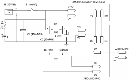
The operation of the system is very simple and does not require explanation. When power is supplied to the system, it goes into standby mode. When J2 connector pins are shorted, a pre-programmed warning message is sent to the required mobile number. You can connect any intrusion detector (such as a light guard or motion sensor) to the J2 input connector. Note that an active-low (L) signal on pin 1 of connector J2 will activate the burglar alarm.
Moreover, an optional “call-alarm” device has been added to the system. It activates a telephone call when the user presses the S2 button (or when another electronic unit initiates an alarm). After pressing the “call” button (S2), the call can be canceled by pressing another button S3 – the “end” button. This option can be used to generate a “missed call” alarm in case of intrusion.
The circuit is very flexible, so it can use any SIM900A modem (and, of course, the Arduino Uno board). Please read the modem documentation carefully before starting assembly. This will make the system manufacturing process easier and more enjoyable.
List of radioelements
| Designation | Type | Denomination | Quantity | Note | Shop | My notepad |
|---|---|---|---|---|---|---|
| Arduino board | Arduino Uno | 1 | To notepad | |||
| GSM/GPRS modem | SIM900A | 1 | To notepad | |||
| IC1 | Linear regulator | LM7805 | 1 | To notepad | ||
| C1 | 100uF 25V | 1 | To notepad | |||
| C2 | Electrolytic capacitor | 10uF 16V | 1 | To notepad | ||
| R1 | Resistor | 1 kOhm | 1 | To notepad | ||
| LED1 | Light-emitting diode | 1 | To notepad | |||
| S1 | Button | With fixation | 1 |