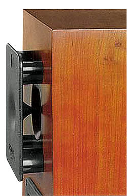
You can use any solid tubes as a phase inverter for acoustics. In non-professional practice, plastic tubes used for internal sewers. The diameters of such tubes are standard. However, sometimes this set is not enough, for example, when a phase inverter of a certain diameter is needed.
Then the pipe will have to be produced by yourself.
By the way, before starting the manufacture of the phase inverter pipe, I advise you to cover the table on which you are making with newsprint.
To make a phase inverter calculation and make a pipe, we need:
Initially, 3-4 layers of thin newsprint must be wound onto the mandrel. In order for it not to unwind, it is necessary to strengthen the seam with PVA glue. All layers of paper are tightly adjacent to the mandrel, and there should be no air or glue between them.
Then, from this sheet of whatman paper, you need to cut a strip, moreover, the width of which would be combined with the length of your future pipe.
By the way, the length of the strip must be sufficient to wind it on the mandrel in 5-6 turns.
After that, it is appropriate to prepare the epoxy adhesive, for this you need to mix the resin and hardener in proportions according to the instructions (10: 1).
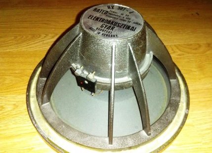
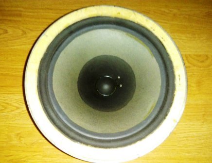
speakers Beag HX 301 - 4
For the correct determination of the volume of glue and resin, it is better to use syringes. In order to prevent the components from mixing in their containers, prepare separate syringes for resins and hardeners.
You need to put on gloves and start winding the layers of paper on a specially prepared mandrel, gluing them with epoxy glue. Note that the 1st turn does not need to be glued to the mandrel! You can apply the resin directly with a glove: easily dip your hand into the glue and apply it to the surface.
You need to wind 5-6 turns of drawing paper.
In order for the layers to better adjoin each other, pull elastic bands over this product or wrap it with a thread. The pipe should dry upright for about a day.
Do-it-yourself phase inverter - it's easy and simple!
You can test the phase inverter
Subscribe, comment, share in social networks. Good luck finding your sound!
Download new albums - in good quality
Editor's Note: The article by an Italian acoustics specialist, reproduced here with the blessing of the author, was originally titled Teoria e pratica del condotto di accordo. That is, in literal translation - "Theory and practice of a phase inverter." This title, in our opinion, corresponded to the content of the article only formally. Really, we are talking about the relationship between the simplest theoretical model of a phase inverter and those surprises that practice is preparing. But this is if it is formal and superficial. But in essence, the article contains an answer to questions that arise, judging by the editorial mail, all the time when calculating and manufacturing a phase inverter subwoofer. Question one: “If you calculate a phase inverter using a formula known for a long time, will the finished phase inverter have the calculated frequency?” Our Italian colleague, who has eaten about a dozen dogs on phase inverters in his lifetime, replies: “No, it won’t work.” And then he explains why and, most importantly, how much it will not work. Question two: “I calculated the tunnel, but it is so long that it does not fit anywhere. How to be? And here the signor offers so much original solutions that it is precisely this side of his works that we put in the headline. So the key word in the new title should not be understood in the new Russian way (otherwise we would have written: “in short, a phase inverter”), but quite literally. Geometrically. And now Signor Matarazzo has the floor to speak.
Phase inverter: in short!
Jean-Piero MATARAZZO Translated from Italian by E. Zhurkova
About the author: Jean-Pierro Matarazzo was born in 1953 in Avellino, Italy. Since the early 70s he has been working in the field of professional acoustics. Long years was in charge of testing acoustic systems for Suono (Sound) magazine. In the 90s, he developed a number of new mathematical models of the process of sound emission by loudspeaker diffusers and several projects of acoustic systems for industry, including the Opera model, popular in Italy. Since the late 90s, he has been actively collaborating with the magazines "Audio Review", "Digital Video" and, most importantly for us, "ACS" ("Audio Car Stereo"). In all three, he is in charge of measuring parameters and testing acoustics. What else? .. Married. Two sons are growing, 7 years old and 10.
Fig 1. Diagram of a Helmholtz resonator. That from which everything comes.
![]()
Fig 2. The classic design of the phase inverter. In this case, the influence of the wall is often not taken into account.
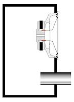
Fig 3. Phase inverter with a tunnel, the ends of which are in free space. There is no wall effect here.
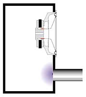
Fig 4. You can bring the tunnel completely out. Here again there will be a "virtual elongation".
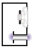
Fig 5. You can get a "virtual extension" at both ends of the tunnel by making another flange.
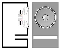
Figure 6. Slot tunnel located far from the walls of the box.
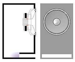
Figure 7. Slot tunnel located near the wall. As a result of the influence of the wall, its “acoustic” length is greater than the geometric one.
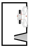
Figure 8. Tunnel in the form of a truncated cone.

Figure 9. The main dimensions of the conical tunnel.
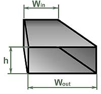
Figure 10. Dimensions of the slotted version of the conical tunnel.
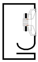
Fig 11. Exponential tunnel.
![]()
Figure 12. Tunnel in the shape of an hourglass.

Figure 13. The main dimensions of the tunnel in the form of an hourglass.
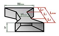
Figure 14. Slotted version of the hourglass.
Magic formulas
One of the most common wishes in the author's e-mail is to give a "magic formula", according to which the ACS reader could calculate the phase inverter himself. This is, in principle, not difficult. The phase inverter is one of the implementations of a device called the "Helmholtz resonator". The formula for its calculation is not much more complicated than the most common and accessible model of such a resonator. An empty Coca-Cola bottle (only a bottle, not an aluminum can) is just such a resonator, tuned to a frequency of 185 Hz, this has been verified. However, the Helmholtz resonator is much older than even this packaging of a popular drink, which is gradually becoming obsolete. However, classical scheme the Helmholtz resonator is similar to a bottle (Fig. 1). In order for such a resonator to work, it is important that it has a volume V and a tunnel with a cross-sectional area S and a length L. Knowing this, the tuning frequency of the Helmholtz resonator (or phase inverter, which is the same thing) can now be calculated by the formula:
![]()
where Fb is the tuning frequency in Hz, s is the speed of sound equal to 344 m/s, S is the area of the tunnel in sq. m, L is the length of the tunnel in m, V is the volume of the box in cubic meters. m. \u003d 3.14, this goes without saying.
This formula is really magical, in the sense that the bass reflex setting does not depend on the parameters of the speaker that will be installed in it. The volume of the box and the dimensions of the tunnel determine the frequency of tuning once and for all. Everything seemed to be done. Let's get started. Suppose we have a box with a volume of 50 liters. We want to turn it into a bass reflex box tuned to 50Hz. We decided to make the tunnel diameter 8 cm. According to the formula just given, the tuning frequency of 50 Hz will be obtained if the length of the tunnel is 12.05 cm. We carefully manufacture all the parts, assemble them into a structure, as in fig. 2, and for verification we measure the actually resulting resonant frequency of the phase inverter. And we see, to our surprise, that it is not 50 Hz, as it should be according to the formula, but 41 Hz. What's wrong and where did we go wrong? Yes, nowhere. Our freshly built phase inverter would be tuned to a frequency close to that obtained by the Helmholtz formula if it were made, as shown in Fig. 3. This case is closest to the ideal model described by the formula: here both ends of the tunnel "hang in the air", relatively far from any obstacles. In our design, one of the ends of the tunnel mates with the wall of the box. For the air oscillating in the tunnel, this is not indifferent, because of the influence of the "flange" at the end of the tunnel, it seems to be its virtual elongation. The phase inverter will be configured as if the length of the tunnel was 18 cm, and not 12, as it really is.
Note that the same thing will happen if the tunnel is completely placed outside the box, again aligning one of its ends with the wall (Fig. 4). There is an empirical dependence of the "virtual elongation" of the tunnel depending on its size. For a circular tunnel, one cut of which is located far enough from the walls of the box (or other obstacles), and the other is in the plane of the wall, this elongation is approximately equal to 0.85D.
Now, if we substitute all the constants into the Helmholtz formula, introduce a correction for “virtual elongation”, and express all dimensions in familiar units, the final formula for the length of the tunnel with a diameter D, which ensures that a box of volume V is tuned to a frequency Fb, will look like this:
Here the frequency is in hertz, the volume is in liters, and the length and diameter of the tunnel are in millimeters, as we are used to.
The result obtained is valuable not only because it allows at the calculation stage to obtain a length value close to the final one, giving the required value of the tuning frequency, but also because it opens up certain reserves for shortening the tunnel. We have already won almost one diameter. It is possible to shorten the tunnel even further while maintaining the same tuning frequency by making flanges at both ends, as shown in fig. five.
Now, everything seems to be taken into account, and, armed with this formula, we seem to be omnipotent. This is where we face difficulties.
First difficulties
The first (and main) difficulty is as follows: if a relatively small box needs to be tuned to a fairly low frequency, then by substituting a large diameter into the formula for the length of the tunnel, we will get a large length. Let's try to substitute a smaller diameter - and everything turns out fine. Large diameter requires great length, and the small one is just small. What's wrong with that? And here's what. Moving, the speaker cone with its back side "pushes" almost incompressible air through the phase inverter tunnel. Since the volume of oscillating air is constant, the air velocity in the tunnel will be as many times greater than the oscillatory velocity of the diffuser, as many times the cross-sectional area of the tunnel less area diffuser. If you make a tunnel ten times smaller than a diffuser, the flow velocity in it will be high, and when it reaches 25–27 meters per second, turbulence and jet noise will inevitably appear. The great researcher of acoustic systems R. Small showed that the minimum section of the tunnel depends on the diameter of the speaker, the largest stroke of its cone and the tuning frequency of the phase inverter. Small proposed a completely empirical, but trouble-free formula for calculating minimum size tunnel:
Small derived his formula in units familiar to him, so that the diameter of the speaker Ds, the maximum cone travel Xmax and minimum diameter Dmin tunnels are expressed in inches. The bass reflex tuning frequency is, as usual, in hertz.
Now things don't look as rosy as before. It often turns out that if you choose the right diameter of the tunnel, it comes out incredibly long. And if you reduce the diameter, there is a chance that already at medium power the tunnel will “whistle”. In addition to the actual jet noise, tunnels of small diameter also have a tendency to so-called "organ resonances", the frequency of which is much higher than the tuning frequency of the phase inverter and which are excited in the tunnel by turbulences at high flow rates.
Faced with this dilemma, ACS readers usually call the editor and ask for a solution. I have three of them: easy, medium and extreme.
A simple solution for small problems
When the estimated length of the tunnel is such that it almost fits in the hull and only slightly shortens its length with the same setting and cross-sectional area, I recommend using a slotted tunnel instead of a round one, and placing it not in the middle of the front wall of the hull (as in Fig. 6 ), but close to one of the side walls (as in Fig. 7). Then at the end of the tunnel, located inside the box, the effect of "virtual elongation" will be affected due to the wall located next to it. Experiments show that with a constant cross-sectional area and tuning frequency, the tunnel shown in Fig. 7 is about 15% shorter than with the construction as in fig. 6. A slotted phase inverter, in principle, is less prone to organ resonances than a round one, but to protect yourself even more, I recommend installing sound-absorbing elements inside the tunnel, in the form of narrow strips of felt glued to inner surface tunnel in the region of a third of its length. This is a simple solution. If it is not enough, you will have to go to the average.
Medium solution for bigger problems
An intermediate complexity solution is to use a truncated cone tunnel, as in Fig. 8. My experiments with such tunnels have shown that here it is possible to reduce the cross-sectional area of the inlet compared to the minimum allowable according to the Small formula without the danger of jet noise. In addition, a conical tunnel is much less prone to organ resonances than a cylindrical one.
In 1995 I wrote a program for calculating conical tunnels. It replaces a conical tunnel with a sequence of cylindrical ones and, by successive approximations, calculates the length required to replace a regular constant section tunnel. This program is made for everyone, and it can be downloaded from the ACS magazine website http://www.audiocarstereo.it/ in the ACS Software section. A small program that runs under DOS, you can download and calculate it yourself. And you can do it differently. When preparing the Russian version of this article, the results of calculations using the CONICO program were summarized in a table, from which you can take the finished version. The table is compiled for a tunnel with a diameter of 80 mm. This diameter value is suitable for most subwoofers with a cone diameter of 250 mm. After calculating the required length of the tunnel using the formula, find this value in the first column. For example, according to your calculations, it turned out that you need a tunnel 400 mm long, for example, to tune a box with a volume of 30 liters to a frequency of 33 Hz. The project is not trivial, and it will not be easy to place such a tunnel inside such a box. Now look at the next three columns. It shows the dimensions of the equivalent conical tunnel calculated by the program, the length of which will no longer be 400, but only 250 mm. Quite another matter. What the dimensions in the table mean is shown in fig. nine.
![]()
Table 2 is compiled for the initial tunnel with a diameter of 100 mm. This will fit most subwoofers with a 300mm driver.
If you decide to use the program yourself, remember: a truncated cone-shaped tunnel is made with an inclination angle of the generatrix a from 2 to 4 degrees. This angle of more than 6 - 8 degrees is not recommended, in this case, turbulence and jet noise may occur at the entrance (narrow) end of the tunnel. However, even with a small taper, the reduction in the length of the tunnel is quite significant.
A tunnel in the form of a truncated cone does not have to have a circular cross section. Like a regular, cylindrical one, it is sometimes more convenient to make it in the form of a slotted one. Even, as a rule, it is more convenient, because then it is assembled from flat parts. The dimensions of the slotted version of the conical tunnel are given in the following columns of the table, and what these dimensions mean is shown in fig. 10.
Replacing a conventional tunnel with a conical one can solve many problems. But not all. Sometimes the length of the tunnel turns out to be so large that even shortening it by 30 - 35% is not enough. For these difficult cases...
Extreme solution for big problems
An extreme solution is to use a tunnel with exponential contours, as shown in Fig. 11. For such a tunnel, the cross-sectional area first gradually decreases, and then just as smoothly increases to the maximum. From the point of view of compactness for a given tuning frequency, resistance to jet noise and organ resonances, the exponential tunnel has no equal. But it has no equal in terms of manufacturing complexity, even if its contours are calculated according to the same principle as was done in the case of a conical tunnel. In order to still be able to take advantage of the exponential tunnel in practice, I came up with its modification: a tunnel, which I called the "hourglass" (Fig. 12). The hourglass tunnel consists of a cylindrical section and two conical ones, hence the outward resemblance to an ancient instrument for measuring time. This geometry makes it possible to shorten the tunnel compared to the original, constant section, at least one and a half times, or even more. To calculate the hourglass, I also wrote a program, it can be found there, on the ACS website. And just like for a conical tunnel, here is a table with ready-made options calculation.
What the dimensions in tables 3 and 4 mean will become clear from fig. 13. D and d are the diameter of the cylindrical section and the largest diameter of the conical section, respectively, L1 and L2 are the lengths of the sections. Lmax is the full length of the hourglass tunnel, just for comparison, how much shorter it was made, but in general, it is L1 + 2L2.
Technologically, making an hourglass with a circular cross section is not always easy and convenient. Therefore, here it can also be made in the form of a profiled slot, it will turn out, as in Fig. 14. To replace a tunnel with a diameter of 80 mm, I recommend choosing a slot height of 50 mm, and for replacing a 100 mm cylindrical tunnel, 60 mm. Then the width of the section of constant section Wmin and the maximum width at the entrance and exit of the tunnel Wmax will be the same as in the table (section lengths L1 and L2 - as in the case of round section, nothing changes here). If necessary, the slot tunnel height h can be changed by simultaneously adjusting both Wmin and Wmax so that the values of the cross-sectional area (h.Wmin, h.Wmax) remain unchanged.
I used the hourglass tunnel variant of the phase inverter, for example, when I was making a home theater subwoofer with a tuning frequency of 17 Hz. The estimated length of the tunnel turned out to be more than a meter, and by calculating the "hourglass", I was able to reduce it by almost half, while there was no noise even at a power of about 100 watts. Hope this helps you too...
The logical finale of the phase inverter saga will be the practical aspects of its implementation. The key element here is precisely the pipe, which is also a tunnel, which, as a result of slave transliteration from English, is a port. It is she, the pipe, that will make it possible to put into practice two main parameters that determine the acoustic appearance of the conceived phase inverter: the volume of the case and the frequency of its tuning. These two values, one in liters, the second in hertz, are the result of either an independent calculation or following previously made calculations. They may come from speaker manufacturers, our tests, or expert advice based on their practice. In all three cases, it happens that ready-made tunnel dimensions are given that ensure that a known volume is tuned to the desired frequency, but, firstly, not every time, and secondly, blind copying is not always possible and always not commendable. So the following statement of the problem will be more general and much more productive: the volume and frequency are known, and we will solve the question of their physical, in material, implementation on our own. Part of the story will be organized according to the principle of questions and answers: the nomenclature of questions is known, they are repeated in the editorial mail with regularity, giving rise to statistical calculations that our test department loves so much. I will not take away their favorite toy, we have ours. So, what at first, we calculate the tunnel or buy a pipe, which this tunnel will become? In theory, you must first buy - pipes are not of any diameter, but from a certain range of values, if you take ready-made ones, and not wrap it yourself from paper on glue, like a pioneer from a young cosmonaut's circle. But you still have to start with at least a rough estimate, and the point here is that ...
Thickness Matters
If the tunnel is really a pipe (there are options, after all), what should its diameter be? The most general and crudest answer is: the more, the better. The advice is really radical and can cause a protest reaction: what if I take and make a tunnel twice the diameter of the speaker? You won’t take it and you won’t do it, no matter how hard you try, more than a hundred years ago, a certain Herman Helmholtz took care of this, the resonator of whose name the phase inverter is, and later the creators of cars, who made them smaller in size than the steam locomotives that existed at that time. So, in order, why more and why something will stop this process.
During operation, near the tuning frequency, where, in fact, the phase inverter tunnel performs its functions, adding from itself to the sound waves generated by the vibrations of the diffuser, air moves inside the tunnel. Moves oscillatingly, back and forth. The volume of moving air is exactly the same as that during each oscillation is set in motion by the diffuser, it is equal to the product of the diffuser area and its stroke. For a tunnel, this volume is the product of the cross-sectional area and the air flow inside the tunnel. The cross-sectional area is really always less than the diffuser area (if someone has not yet abandoned the threat to make the same, or even more, they will soon not go anywhere and refuse), and in order to move the same volume, the air needs to move faster, the speed in the tunnel decreases diameter increases in proportion to the decrease in its cross-sectional area. Why is it bad? Everyone at once. First of all, the fact that the Helmholtz resonator model, on which everything is based, assumes that there is no energy loss due to air friction against the tunnel walls. This is, of course, an ideal case, but the farther we go from it, the less work phase inverter will be like what we expect from him. And the friction losses in the tunnel are the higher, the greater the air speed inside. Theoretically, the formula, and the simple program based on it, does not take into account these losses and will meekly give you the estimated length of the tunnel with a diameter of at least a finger, but such a phase inverter will not work, everything will die in the whirlwinds of air trying to rapidly fly back through the narrow tunnel - forward. The text of the traffic police propaganda poster I once saw “Speed is death” certainly fits the movement of air in the tunnel, if death is attributed to the efficiency of the phase inverter.
However, much earlier than the fazik dies as a means of sound reproduction, it will become a source of sounds for which it is not intended, vortices that occur when excessive high speed air movements will create jet noises that disturb the harmony of bass sounds in the most unscrupulous and unaesthetic way.
What should be taken as the minimum value of the tunnel cross-sectional area? In different sources you will find different recommendations, not all of them have ever been tested by the authors, at least through a computational experiment, let alone others. As a rule, two values are included in such recommendations: the diameter of the diffuser and the maximum value of its stroke, that is Xmax. This is reasonable and logical, but fully applies only to the operation of the subwoofer at the limit, when it is already a little too late to talk about sound quality. Based on numerous practical observations, a much simpler rule can be adopted, it is not perfect and not entirely universal, but it works: for an 8-inch head, the tunnel must be at least 5 cm in diameter, for a 10-inch -
7 cm, for 12 and more - 10 cm. Is it possible to do more? It is even necessary, but right now something will stop us. Namely, the length of the tunnel. The fact is that...
Length matters
As said, it will be commanded by the great Hermann von Helmholtz. Here he is, at the blackboard at the University of Heidelberg, and on the blackboard is the same formula. Well, this time I wrote it, but I came up with it - he would have written it in the same way. This uncomplicated, since it was derived for the ideal case, the dependence shows what the resonance frequency of a certain cavity will be (we are more familiar with a box, although Hermann von made such bubbles with tail pipes) depending on the volume V, length L and cross-sectional area of the tail. Please note: there are no speaker parameters here, and it would be strange if they were. In any case, it is useful to remember and never succumb to provocations: the phase inverter setting is completely and exhaustively determined by the size of the box and the characteristics of the tunnel connecting this box with environment. In addition, the formula includes only the speed of sound in the atmosphere of the planet Earth, denoted by "c", and the number "pi", which does not even depend on the planet.
For practical purposes, namely, calculating the length of the tunnel from known data, the formula is easy to convert, remembering your native school, and substitute the constants as numbers. Many did it. Many have published the results of this exciting process, and the author is a little surprised how spectacularly it was possible to crap out in an operation with three or four numbers. In general, a third of the converted formulas published on paper and on the Web are incomprehensibly nonsense. The correct one is given here if we substitute the values in units shown in black.
The same formula, plus some corrections, is included in all known programs for calculating phase inverters, but right now the formula is more convenient for us, everything is in plain sight. Look: what will happen if instead of a minimalist tunnel we put another, more spacious (and therefore better)? The required length will increase in proportion to the square of the diameter (or in proportion to the area, but we are going to buy a pipe by diameter, they don’t sell it differently). We switched from a 5 cm pipe to a 7 cm pipe, for example, the length with the same setting will need twice as much. We switched to 10 cm - four times. Trouble? So far - half the trouble. The fact is that...
Caliber matters
There will be trouble now. Once again we look at the formula, this time - at the denominator, focus your eyesight. All other things being equal, the length of the tunnel will be the greater, the smaller the volume of the box. If, in order to tune a 100-liter volume to 30 Hz, having a 100 mm plumbing pipe, it is necessary to open and paste a piece of shit pipe with a length of 25 centimeters into the box, then with a box volume of 50 liters it will be half a meter (which is no less than half the trouble), and with a fairly common 25 liters, a tunnel of this thickness will have to have a meter length. This is a disaster, no options.
In our practical conditions, the volume of the box is primarily determined by the parameters of the speaker, and for reasons that are already well known to readers of this series, for 8-inch heads, the optimal volume rarely exceeds 20 liters, for "tens" - 30 - 40, only when it comes to comes to 12-inch caliber, we start to deal with volumes of the order of 50 - 60 liters, and then not always.
So it turns out some kind of parade of sovereignties: the tuning frequency of the FI is determined by the bass that we want to get from it, whether it is on the “eight” or on the “tag” - it doesn’t matter. And the box tuning frequency again does not depend on the speaker, the smaller the volume, the longer the tunnel. The result of the parade: as we have repeatedly noticed in tests of small-caliber subwoofers, it is physically impossible (or difficult) to implement the desirable and promising design option in FI. Even if you don’t feel sorry for the space in the trunk, you can’t make the volume of the FI box larger than the optimal one, and the optimal one often turns out to be so small that it’s unthinkable to tune it to a frequency of 30–40 Hz that is invariant to other factors. Here is an example from a recent test of 10-inch subwoofer heads (“A3” No. 11/2006): if we take a pipe diameter of 7 cm as an axiom, then in order to make a phase inverter on a Boston head, it would take a piece 50 cm long, for Rainbow - 70 cm, And for Rockford Fosgate and Lightning Audio - about a meter. Compare with the recommendations in this issue's test for 15-inch heads: none of these problems were noted. Why? Not because of the speaker, as such, but because of the original volume selected by the speaker parameters. What to do? Face adversity head on. Weapons were forged for us by generations of specialists (and not only). Do you know what's the matter here?
Form matters
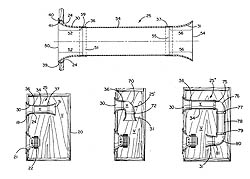
You could hardly fail to notice: I really like to delve into patents, because I think that even the road from invention to real life not so short, the patent is a reflection of thought in the form of a vector, that is, taking into account the direction. Most of the innovations proposed (and steadily proposed) by tireless minds in relation to the phase inverter are concentrated on combating two interfering factors: the length of the tunnel, when its cross section is large, and jet noise, when its cross section, trying to reduce the length, tried to reduce. The first, simplest solution, the admissibility of which we are asked in an editorial mail five times a month: can the tunnel be placed not inside the box, but outside? Here is the answer, final, factual and real, like a paper on Professor Preobrazhensky's apartment: you can. At least partially, at least in its entirety, the tunnel was stuffed inside the box solely for aesthetic reasons, at von Helmholtz it stuck out from the outside, and nothing, he survived it. Yes, and our modernity gives examples: for example, car audio veterans cannot help but remember (many, to be honest, cannot forget) the SAS Bazooka bass pipes. After all, they began with a patent for a subwoofer, which is conveniently placed behind the seat of a truck - the favorite transport of Americans. To do this, the inventor stretched the phase inverter pipe along the outside of the case, at the same time giving it a shape spread over the surface of the cylindrical case. This is one example, there is another: some companies that produce built-in subwoofers for home theaters bring out the tube-tunnel of a bandpass subwoofer. subwoofer type in this case it doesn't matter: it's the same name resonator you know who. Another solution is also, judging by the letters, they are looking for, but they are afraid. "Is it possible to bend the tunnel?" The answer is in the style of Philip Philipovich and is obvious. Otherwise, several companies would not release at once (DLS, JL Audio, Autoleads, etc. etc.) flexible pipes specifically for this purpose. And in the field of patent documentation, there is even an interesting hint on how this problem can be solved not without grace and material savings: at one time, the design of a model tunnel was proposed, which would be assembled from standard elements in any desired form, the illustration will tell the rest. I’ll add on my own: most of the details depicted in the patent are touchingly reminiscent of the nomenclature of the elements of sewer networks of local importance, which is a practical recipe for introducing the intellectual excess of the American inventor.
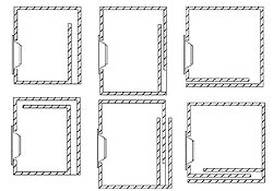
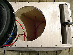
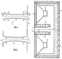
Struggling with the inappropriate length of the tunnel, they often follow the path of building the so-called "slotted ports", their advantage is in constructive integration with the hull, which allows, with a certain imagination, to make the tunnel quite long, on the attached diagram there are several options at once, which the question is, of course, it is far from being exhausted (the top three sketches were written by the famous high-end artist Alexander Klyachin, the rest was a matter of technique).
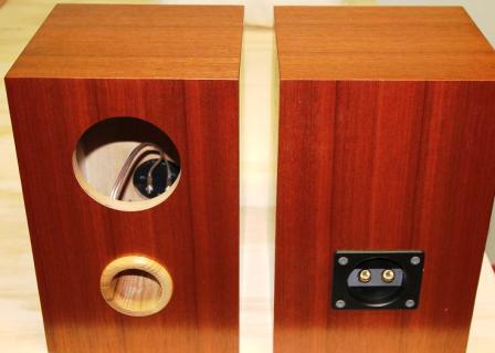
The disadvantage of slots is the difficulty of adjusting the length, this is not plumbing PVC - he waved the saw, and it's in the bag. But there are solutions here too: not so long ago, one of the heroes of the “Own Game” column, Alexander Sultanbekov from Perm (it’s not a sin to once again remind the country of the names of its heroes) demonstrated in practice how you can adjust the slotted port by changing its cross section with a constant length, he is did by laying plywood spacers inside, as shown in the photo somewhere nearby, look.
In folding the bass reflex tunnel, some bright minds went to extremes: one bright mind suggested, for example, to roll the tunnel in the form of a spiral around the cylindrical body of the loudspeaker, the other responded to the cunning Helmholtz formula with a screw tunnel, such a concept is familiar to us here in Russia...
But in general, all these solutions (even with a screw) are frontal, here a tunnel of constant length is simply attached or folded so that it does not interfere. Known (and even sold in commercial quantities) implementation of another principle. Here's the thing here.
Cross section matters
Not the area, as such, but the nature of its change along the length of the tunnel. Until now, we, guided by the teachings of von Helmholtz in its simplest, school form, considered it indispensable that the cross section of the tunnel is constant. And there were people who violated this condition and even made money on it.
Experienced readers will remember, for example, an article by our Italian colleague, Professor Matarazzi, where he suggests effective solutions to reduce the length of the tunnel by giving it a conical or doubly conical hourglass shape. In "A3" No. 10/2001, the calculations for the professor's programs are given in the form of tables, and the senior recently found and sent the programs themselves at our request. By the time this issue goes out of print, we will put them on the site in the "Appendices" section. True, the absent-minded professor lost the source code forever, so the programs remain in Italian, if anyone knows how to translate without having the code, we will accept the help with gratitude.
In the meantime, we note: in his research, the professor is not the first, and not the only one. Even whole tragedies occurred in this direction. Longtime readers of the magazine may remember the note in "A3" No. 2/2003 about the lawsuit over the bass reflex tunnel, not so long ago I remind you: Bose Corporation saw that another corporation, JBL, using in its columns bass reflex tunnels with a curvilinear generatrix, called Linear-A, has gravely infringed upon the intellectual property of Bose Corp. As evidence, a US patent was cited, which mentioned, among other things, that it would be nice to make a tunnel with an elliptical generatrix, then it would be both shorter and quieter in terms of jet noise. In vain JBL tried to explain to the court that Bose has an ellipse, and JBL has an exponent. The court explained that ellipses-schmellipses are the tenth thing, and a lot of speakers were sold, Bose's accounting department calculated: JBL's profit was $5,676,718 and 32 cents, which was proposed to be paid to the offended party's cashier. They brought it in as nice ones, including coppers, and in all columns the tunnels changed to others, FreeFlow, like an improved model. Here's how it goes...
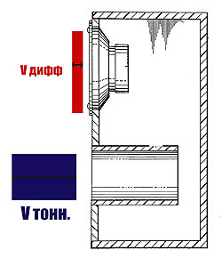
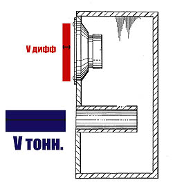
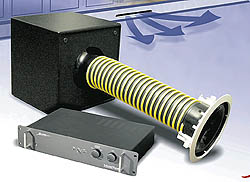
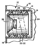
Very, very many people have suggested avoiding the cylinder as a form of tunnel. Some - in the style of Matarazzi with variations, some - on a modest, local scale, limiting themselves to giving curvilinear contours to the ends of a cylindrical tunnel in order to reduce jet noise from turbulence. The most radical means of dealing with both length and noise was not only invented, but has been exclusively used for more than one year by Matthew Polk, the founder of a company named after himself. The essence of the device called PowerPort is as follows: part of the functions of the tunnel is taken over by one or two, at each end of the pipe, an annular gap between the wall of the box and a “mushroom” placed at a strictly calculated distance from it, however, everything is visible in the figure. Almost all Polk Audio home loudspeakers are supplied with such tunnels. And if only someone encroached, his 32 cents cried, plus something else. For myself, my loved ones, no one will forbid trying such a thing, especially since once upon a time Polk posted a spreadsheet in Excel on his corporate website, according to which you can calculate everything, I then popped it from this site (having received later, in hindsight, the blessing of the author - I'm not for the purpose of profit) and even translated the accompanying instructions into the great and mighty, it's all on our website.
A propos, and the works of Professor Matarazzi, and the revolutionary development of Matthew Polk remind us of this: the Helmholtz gymnasium formula, among other things, does not take into account a very significant effect for practice: in the vast majority of cases (almost always) one of the ends of the tunnel is adjacent to the wall subwoofer enclosure, this applies to both round pipes, sawn flush with the wall, and pipes equipped with an aerodynamic ending, and to an even greater extent - slotted ports stuck to the wall. The proximity of the wall creates an end effect reminiscent of what the author of PowerPort intentionally sought - a virtual lengthening of the tunnel. Therefore, to the formula directly derived from the works of von Helmholtz, modern applied specialists recommend introducing an amendment, purely empirical, but no less necessary, it is highlighted in red so that it is clear where the classic of the 19th century is, and where is the practice of the 20th.
But in general, dear friends, it's time to get down to business, it's not a century to delve into pieces of paper. The point is just this...
On the issue of thickness: pushing the same volume of air through a tighter tunnel, it will have to be accelerated to a higher speed. And "speed is death"
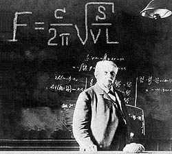
Helmholtz would have written his formula in exactly the same way, just at that moment there was no photographer
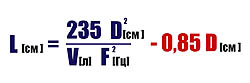
The final and actual formula that replaces the computer program. She is correct, checked repeatedly. The meaning of the tail highlighted in red will be explained in the text.

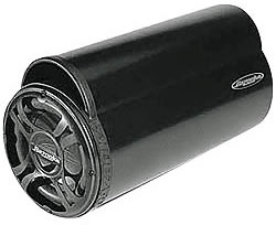
Can the tunnel be outside the box? Yes, the whole company built its business on this, the patent for a convenient subwoofer was replicated by groans of thousands of SAS Bazooka bass pipes. And manufacturers of built-in subwoofers for home theaters don't care at all...
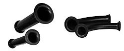
Is it possible to leave the tunnel inside, but bend it as it is more convenient? Here is your answer

Exotic, desperate solutions: spiral or screw tunnel
The slot tunnel is integrated with the drawer, so it can be made longer than the usual, “plug-in” one, adjusting the length, however, is much more difficult ...
This means that it is necessary to adjust not the length, but the cross section: this is how one resident of the capital did it Perm Territory

Departure from the cylindrical shape of the tunnel was proposed both to reduce its length, and in the form of a local "aerodynamic treatment" to reduce jet noise.
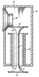
The most effective solution in this area: Matthew Polk's PowerPort. The invention did not remain on paper, it is component almost all Polk Audio speakers
Prepared based on the materials of the magazine "Avtozvuk", February 2007.www.avtozvuk.com
The method of calculating the acoustic phase inverter Yu. Lyubimov based on the materials of the journal "EW" (R-7/68) is based on the simplest measurements carried out with a well-defined copy of the loudspeaker installed in the acoustic phase inverter and on the nomographic determination of the dimensions of the latter.
First of all, guided by Fig. 1 and the table, it is necessary to make a "standard volume" - a sealed plywood box, all joints of which are carefully fitted, glued and smeared with plasticine to avoid air leaks. Next, measure the natural resonance frequency of the loudspeaker located in free space. To do this, it is suspended in the air away from large objects (furniture, walls, ceiling).
| diffuser diameter loudspeaker, mm |
Dimensions, mm | ||
| A | AT | FROM | |
| 200 | 255 | 220 | 170 |
| 250 | 360 | 220 | 220 |
| 300 | 360 | 220 | 270 |
| 375 | 510 | 220 | 335 |
The measurement scheme is shown in Fig.2. Here ZG is a graduated sound generator, V is an AC tube voltmeter and R is a resistor with a resistance of 100 ... 1000 Ohms (for large resistance values, the measurement is more accurate). By rotating the frequency adjustment knob of the sound generator in the range from 15 ... 20 to 200 ... 250 Hz, the maximum deviation of the voltmeter needle is achieved. The frequency at which the deviation is maximum is the resonant frequency of the loudspeaker in free space FB.
The next step is to determine the resonant frequency of the loudspeaker FЯ, when it works at the "standard volume". To do this, the loudspeaker is placed with a diffuser on the "standard volume" hole and pressed lightly to avoid air leaks at the junction of the surfaces. The method for determining the resonance frequency is the same, but in this case it will be 2-4 times higher.
Knowing these two frequencies, with the help of nomograms, the dimensions of the phase inverter are found. Depending on the diameter of the loudspeaker cone, choose the nomogram shown in Fig. 3 (for a diameter of 200 mm), in Fig. 4 (for a diameter of 250 and 300 mm.) Or
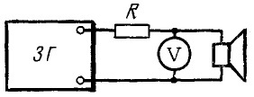
fig.2
In Fig. 5 (for a diameter of 375 mm). According to the selected nomogram, the volume of the phase inverter is determined, for which the points corresponding to the found frequencies are connected by a straight line on the axes "Resonance frequency FВ" (see Fig. 4 point A) and "Resonance frequency FЯ" (point B). The point of intersection C with the minor axis is marked and from here a second straight line is drawn through point D to the "optimal volume" axis. The value corresponding to the new intersection point E is the desired volume. If there are no special considerations for the design of a box of a special configuration, then the calculation internal dimensions it at a given volume can be made according to the nomogram shown in Fig.6. The width of the phase inverter will be equal to 1.4 heights, and the height - 1.4 depths. The use of the nomogram is not difficult: a straight line is drawn between the extreme axes, on which the volume values are plotted. The points of intersection of the line with the axes A, B, C will determine the width, height and depth of the box. Loudspeaker cutout diameter equal to dimension C shown in the table.
Further, having given the diameter of the tunnel, it is necessary to determine its length and check whether it fits into the bass reflex box. The length of the tunnel is found from the graphs shown in Fig. 7 for three internal diameters: graphs A - for a diameter of 50 mm, B - for a diameter of 75 mm to B - for a diameter of 120 mm. By selecting the appropriate graphs, by frequency
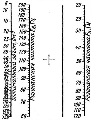
fig.3
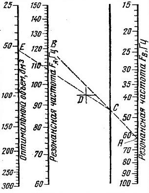
fig.4
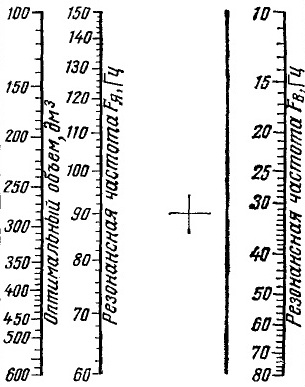
fig.5
FB and the volume of the phase inverter, determined earlier, find the length of the tunnel (example in Fig. 7B). It should be 35-40 mm less than the inner depth of the drawer. If this does not work, you can slightly change the configuration of the box, while maintaining its volume, or take a different diameter of the tunnel.
The phase inverter is made of plywood with a thickness of about 20 mm. If there is no such thick plywood, then to increase rigidity, you need to glue diagonally or crosswise bars of 25 x 75 mm inside the box. The box is assembled with screws and glue, and all seams are sealed. back wall it is recommended to fasten with screws (five pieces per side) with a felt pad. The tunnel is made of thick-walled cardboard tube.
Having made a phase inverter and installing a loudspeaker in it, they begin to dampen it. To do this, it is recommended to completely cover the loudspeaker from the back side with a layer of glass wool 25-50 mm thick, attaching it to the board around the diffuser holder using a ring screwed on with screws or screws. The sufficiency of damping is checked using the circuit shown in Fig. 8. The resistance of the resistor R is taken to be about 0.5 ohm. If the damping coefficient K of the amplifier with which the unit will work is known, and the resistance of the voice coil of the loudspeaker alternating current r, then it can be determined from the formula R = r / K, Ohm.
Moving the switch from one position to another, listen for a click in
I started doing column building in the early 80s. And if at first it was just a “speaker in a box”, then, naturally, the study of the influence of the parameters of the box (and the phase inverter) on the sound of the speaker began.
There are many "subwoofer builders" out there, but for the vast majority it's just a "speaker in a box" and the more the better. Yes, to some extent, for a closed box, this is correct. But for a phase inverter ...
The phase inverter requires careful tuning. What do we see in practice? As a phase inverter, people put sewer pipes of arbitrary length, they make "slotted phase inverters" in the image: "Vasya did this size," while placing another speaker. The one who represents this is limited to the manufacture of a closed box (and he does it right!).
Of course, there are great simulation programs out there like JBL SpeakerShop. But they all require the introduction of a bunch of initial parameters. And even knowing them, the discrepancy with practice turns out, as a rule - huge(the speaker turned out to be slightly different, the box is slightly different in size, we don’t know what and how much filler, the phase inverter pipe is slightly different, we don’t know the acoustic resistance, etc.)
There is a simple technique for setting up a phase inverter that does not require knowledge of the exact initial data of the speakers, boxes, and does not require complex measuring instruments or mathematical calculations. Everything has already been thought out and tested in practice!
I want to talk about a simple method for setting up a phase inverter, which gives an error of no more than 5%. A technique that has existed for over 30 years. I have used it since I was a student.
What is the difference between a box with a phase inverter and a closed box?
Any speaker, like a mechanical system, has its own resonant frequency. Above this frequency, the speaker sounds “pretty smooth”, and below this, the level it creates sound pressure, falls. Falls at a rate of 12 dB per octave (i.e. 4 times for a 2-fold reduction in frequency). The “lower limit of reproducible frequencies” is considered to be the frequency at which the level drops by 6 dB (i.e., 2 times).
Frequency response dynamics in open space
By installing the speaker in a box, its resonant frequency will increase somewhat, due to the fact that the elasticity of the air compressed in the box will be added to the elasticity of the diffuser suspension. Raising the resonant frequency will inevitably "pull" up and the lower limit of the reproducible frequencies. The smaller the volume of air in the box, the higher its elasticity, and, consequently, the higher the resonant frequency. Hence the desire to "make the box more-oh-oh-more."
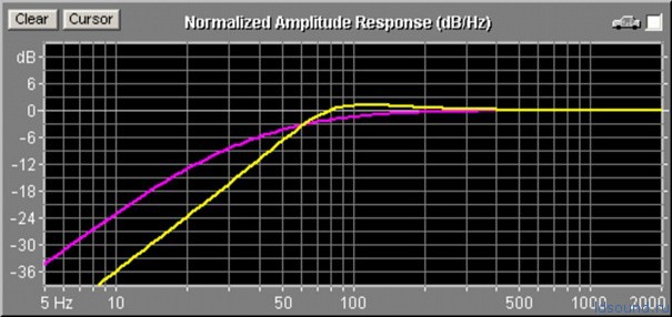
Yellow line - frequency response of the speaker in a closed box
You can make the box "bigger" to some extent without increasing it physical dimensions. To do this, the box is filled with absorbent material. We will not go into the physics of this process, but as the amount of filler increases, the resonant frequency of the speaker in the box decreases (the “equivalent volume” of the box increases). If there is too much filler, then the resonant frequency starts to rise again.
Let's omit the influence of the box dimensions on other parameters, such as the quality factor. Let's leave it to experienced "column builders". In most practical cases, due to limited space, the volume of the box turns out to be quite close to optimal (we don’t build cabinet-sized speakers). And the meaning of the article is not to load you with complex formulas and calculations.
Were distracted. With a closed box, everything is clear, but what does a phase inverter give us? A phase inverter is a “pipe” (not necessarily round, maybe rectangular section and a narrow slot) of a certain length, which, together with the volume of air in the box, has its own resonance. At this “second resonance”, the sound output of the speaker rises. The resonance frequency is chosen slightly lower than the resonance frequency of the speaker in the box, i.e. in the area where the speaker begins to decline in sound pressure. Consequently, where the speaker has a recession, a rise appears, which to some extent compensates for this decline, expanding the lower cutoff frequency of the reproduced frequencies.
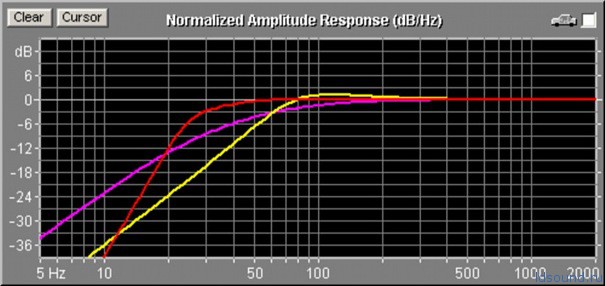
Red line - frequency response of the speaker in a closed box with a phase inverter
It is worth noting that below the resonance frequency of the phase inverter, the sound pressure drop will be steeper than that of a closed box and will be 24 dB per octave.
Thus, the phase inverter allows you to expand the range of reproducible frequencies towards lower frequencies. So how do you choose the resonant frequency of a phase inverter?
If the resonance frequency of the phase inverter is higher than optimal, i.e. it will be close to the resonant frequency of the speaker in the box, then we will get "overcompensation" in the form of a protruding hump in the frequency response. The sound will be barrel-shaped. If the frequency is chosen too low, then the level rise will not be felt, because. at low frequencies, the speaker output drops too much (undercompensated).
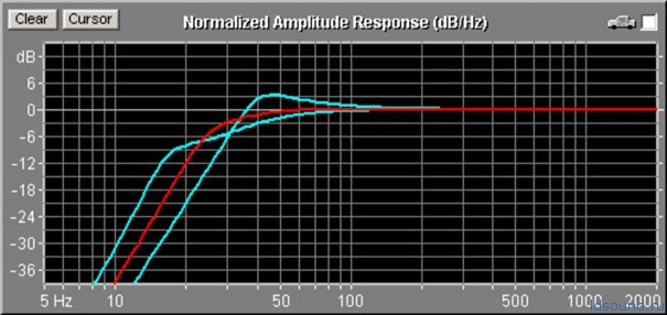
Blue lines - not optimal bass reflex setting
This is a very delicate moment - either the phase inverter will give an effect, or it will not give any, or, conversely, it will ruin the sound! The phase inverter frequency must be chosen very accurately! But where can you get this accuracy in a garage-home environment?
In fact, the coefficient of proportionality between the resonance frequency of the speaker in the box and the resonance frequency of the phase inverter, in the vast majority of real designs, is 0.61 - 0.65, and if we take it equal to 0.63, then the error will be no more than 5%.
1. Vinogradova E.L. "Designing loudspeakers with smoothed frequency response", Moscow, ed. Energy, 1978
2. "More about the calculation and manufacture of a loudspeaker", w. Radio, 1984, No. 10
3. “Setting up phase inverters”, well. Radio, 1986, No. 8
Now let's transfer the theory to practice - it's closer to us.
How to measure the resonant frequency of a speaker in a box? As you know, at the resonant frequency, the “electrical impedance modulus” (Impedance) of the voice coil increases. Roughly speaking, resistance is growing. If for direct current it is, for example, 4 ohms, then at the resonant frequency it will increase to 20 - 60 ohms. How to measure this?
To do this, in series with the speaker, you need to turn on a resistor with a rating an order of magnitude higher than the speaker's own resistance. A resistor with a nominal value of 100 - 1000 ohms is suitable for us. By measuring the voltage across this resistor, we can estimate the "impedance modulus" of the speaker's voice coil. At frequencies where the speaker impedance is high, the voltage across the resistor will be minimal, and vice versa. So, how do you measure?
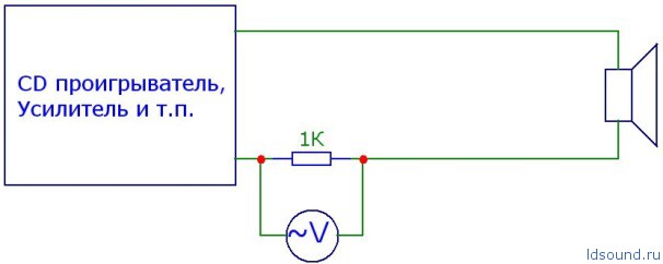
Speaker impedance measurement
Absolute values are not important to us, we just need to find the maximum resistance (minimum voltage across the resistor), the frequencies are quite low, so you can use a regular tester (multimeter) in AC voltage measurement mode. And where to get the source of sound frequencies?
Of course, it is better to use an audio frequency generator as a source ... But let's leave it to professionals. But "no one forbids" us to create a CD with a recorded range of sound frequencies, created in some computer program, such as CoolEdit or Adobe Audition. Even I, with measuring equipment at home, created a CD with 99 tracks, a few seconds each, with a range of frequencies from 21 to 119 Hz, in 1 Hz steps. Very comfortably! I inserted it into the radio, you jump along the tracks - you change the frequency. The frequency is equal to the track number + 20. Very simple!
The process of measuring the resonant frequency of the speaker in the box is as follows: we “plug” the hole of the phase inverter (a piece of plywood and plasticine), turn on the CD for playback, set an acceptable volume, and without changing it, “jump” over the tracks and find the track on which the voltage is on resistor is minimal. Everything - the frequency is known to us.
By the way, in parallel, by measuring the resonant frequency of the speaker in the box, we can choose the optimal amount of filler for the box! Gradually adding the amount of filler, we look at the change in the resonant frequency. We find the optimal amount at which the resonant frequency is minimal.
Knowing the value of the "resonant frequency of the speaker in the box with filler" it is easy to find the optimal resonant frequency of the phase inverter. Just multiply it by 0.63. For example, we got the resonant frequency of the speaker in the box at 62 Hz - therefore, the optimal resonant frequency of the phase inverter will be about 39 Hz.
Now we “open” the opening of the phase inverter, and by changing the length of the pipe (tunnel) or its cross section, we tune the phase inverter to the required frequency. How to do it?
Yes, using the same resistor, tester and CD! You just need to remember that at the resonance frequency of the phase inverter, on the contrary, the “modulus of electrical impedance” of the speaker coil drops to a minimum. Therefore, we need to look not for the minimum voltage across the resistor, but, on the contrary, the maximum - the first maximum, which is below the resonance frequency of the speaker in the box.
Naturally, the tuning frequency of the phase inverter will differ from the required one. And believe me - very strongly ... Usually, towards low frequencies (undercompensation). To increase the tuning frequency of the phase inverter, it is necessary to shorten the tunnel, or reduce its cross-sectional area. You need to do this gradually, half a centimeter ...
Something like this in the low-frequency region will look like the electrical impedance module of the speaker in a box with an optimally tuned phase inverter:
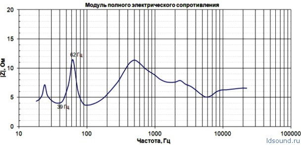
Here is the whole technique. Very simple, and at the same time, giving a fairly accurate result.