The design of enclosures with a bass reflex requires the presence of one or more designed holes. The holes should tune the body to the Fb frequency. This program includes hole size calculations, which makes this task easier.
There are two types of openings commonly used: ports and ducts. A port is a hole cut into the wall of the case (usually the front wall). The hole can be round, square or rectangular. The duct is usually a pipe that is attached to the wall of the housing (usually the front wall). The duct is usually installed flush with the outer surface of the housing.
Both ports and air ducts must be large enough to avoid the introduction of unwanted sounds, such as whistling, created by turbulence of air moving in and out of the case through the port. The size that has the greatest influence on the occurrence of such interference is the cross-sectional area. Bore non-linearity, which reduces power output at high power levels, is also caused by the cross-section being too small. One way to increase the cross-sectional area is to use multiple ports and ducts. The practicality of this method depends on the design you use. How larger area cross-section, the longer the ports or ducts must be. This length often limits the size of the port or duct that can be used in a particular enclosure. This can be one of many challenges when choosing a bass reflex cabinet design, with the cabinet volume Vb and tuning frequency Fb needed to determine the proper bore sizes for a given cabinet.
Excessive duct length can create organ pipe resonance at very high power outputs. Don't use ducts too much long length. One way to reduce the required duct length is to increase the volume of the housing (or the volume of the corresponding chamber). Remember that the resonant frequency of the housing (or chamber) is a derivative of its volume and the dimensions of the duct. If the resonant frequency of the housing is maintained constant, then the smaller the volume of the housing, the longer the air duct should be, and vice versa.
The duct calculation is optimized for ducts in the form of pipes. The algorithm for completing the calculation assumes that the air duct will be fixed flush at one end, and the other end will be far enough from the internal walls to avoid obstructing air circulation. The general rule is to keep the end of the duct at least one diameter away from any side wall or other internal structures. The following table contains some reference values for single duct enclosures.
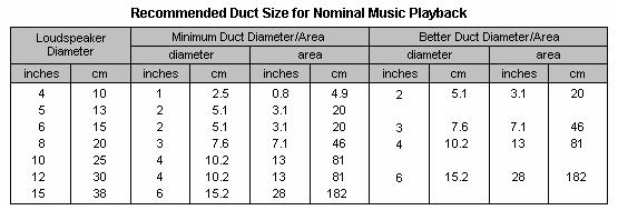
The minimum duct diameter/area in the table is for loudspeakers that travel a distance close to Xmax. When calculating the duct dimensions, the minimum recommended size is obtained to operate without distortion at maximum movement. Note: The minimum recommended duct diameter for a high frequency port in a cabinet design designed to reproduce a particular frequency band may be larger than indicated in the table because air movement through the port has greater velocity at higher frequencies.
To calculate duct dimensions, select Vent from the Box menu or press Ctrl + V. The Vent Dimensions window will open.
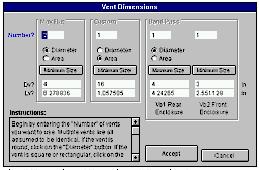
Keep in mind that it has sections for all three bass reflex cabinet designs. If any construct is not used, this section does not appear. Also pay attention to the text instructions. It can be read using the scroll bar.
The Vent Dimensions window is designed to calculate one of two vent sizes, Dv or Lv. First enter the number of ports, select whether Dv will be the diameter or area of the hole, then enter Dv or Lv and the unknown parameter will be automatically calculated. Each of the options is described below.
Vent Parameters
Number: The number of ports you want to use. All ports must be the same size.
Diameter/Area: The size of the first opening, Dv, can be entered as either the diameter (for a circular port or duct) or the cross-section of the opening. When entering given value in area form you can calculate square and rectangular ports.
Minimum Size: Clicking this button will cause the program to recommend you minimum diameter or duct area that will avoid hole noise at maximum speaker deflection. The program also calculates the approximate length of the duct. These recommendations may seem overwhelming because they are based on the maximum deflection of the speaker. If you do not send such a signal to the loudspeaker high level, you can use the more moderate recommendations shown in the table on the previous page.
Dv: Dv can be either the diameter of the hole (if it is circular) or the cross section, depending on which of the Diameter or Area buttons is pressed. Once the Dv value is entered and you move the cursor, the Lv value will be automatically calculated. The Dv value can be entered in inches (square inches if the Area button is pressed) or centimeters (or square centimeters if the Area button is pressed). To change the units of measurement for Dv, double-click the units label.
Important: The hole calculation algorithm is optimized for calculating air ducts with round section. It also works well when calculating air ducts that have square section. With a different cross-sectional shape, for example, a rectangle, when the height and width of the hole are not the same, the calculation will not be entirely accurate. It is not recommended to calculate narrow gaps.
If the Dv value is entered as a cross-sectional area, the value will appear in the corresponding column of the housing spreadsheet with the indication "a" indicating the difference between area and diameter. If the enclosure has multiple ducts or ports, the Dv value will be preceded by the number of ports and an x. For example, two 4-inch diameter ducts are designated 2 x 4.00. Two ports with a cross section of 16 inches are designated 2 x 16.00a.
Lv: Duct length. After entering the Lv value and moving the cursor to another position, the Dv value will be calculated automatically. The Lv value can be entered in inches or centimeters. To change Lv units, double-click the units label.
Sound at the end of the tunnel
“Volodya, if you’re in the warehouse, grab the ports for the phasics...”
(overheard in one of the Moscow installation studios)
In general, in the first issue of any magazine, the reader usually does not expect to see a continuation of any series of articles. But you see, it happens. When Autozvuk was still small and sat under the wing of Salon AV, the first two parts of a trilogy about subwoofers were published - about what to expect from different types of acoustic design and how to choose a speaker for a closed box. (“AV Salon” No. 4 and 5 - 6, 1998).
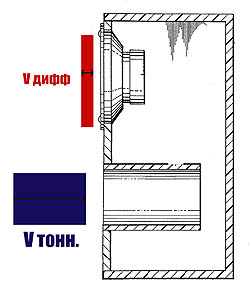
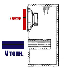
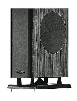
A significant portion of those who, contemplating life, decided to treat the bass armament of their car with understanding, in principle, could already get by with this. But not all. Because there is at least one more, extremely popular type of acoustic design, which is not inferior in popularity to a closed box. Bass reflex in Russian literature, bass reflex, ported box, vented box in English - all this is, in fact, a sound engineering implementation of the Helmholtz resonator idea. The idea is simple: a closed volume is connected to the surrounding space through an opening containing a certain mass of air. It is precisely the existence of this mass - that very column of air that, according to Ostap Bender, puts pressure on any worker, and produces miracles when the Helmholtz resonator is hired to work as part of a subwoofer. Here the sophisticated thing named after the German physicist takes on the prosaic name of a tunnel (in bourgeois - port or vent). How does a bass reflex work? Why does the presence of a neatly made hole of a certain size in the loudspeaker body suddenly have a dramatic effect on the work of the entire ensemble? As already mentioned in passing in the previous parts of this epic canvas, the bass reflex tunnel serves to delay the sound wave arising inside the speaker box for a strictly defined time and release it outside in the same phase as that created by the “front” side of the speaker. Here, in the wild, they will combine their decibels and hit your ears (if calculated correctly) so that it will not seem too little. This is, in fact, why they love the bass reflex - for its increased efficiency compared to a closed box. But not only. Brute force is not an argument unless it is supported by the accuracy of signal reproduction. Here we mean another, significantly less trivial feature of the bass reflex - its ability to produce the required sound pressure with a significantly lower amplitude of diffuser oscillations. This sounds somewhat paradoxical. Everyone knows that it is the presence of a closed volume behind the diffuser that restrains the vibrations of the diffuser, so why will they suddenly appear smaller in a “leaky” housing? And because of the mass, as was said. That's why the hole in the phase converter body is made like a fairly long tunnel - a pipe, in other words, to keep a certain mass of air inside. At relatively high frequencies, above 200 Hz, the inertia of the air mass in the tunnel causes it to be acoustically completely opaque. It's like it's completely blocked.
Lower in frequency airlock in the tunnel begins to come to life and move, as she is pushed from behind by the pulsating pressure inside the box. The inertia of the air mass leads to the fact that it does not move in time with the wave acting on it, but with some shift. It reaches 180 degrees in phase, that is, it begins to be antiphase to the sound wave emanating from the back side of the diffuser at a certain frequency, which is called the bass reflex tuning frequency.

Here, almost all the efforts of the speaker go towards rocking the intractable air mass inside the tunnel, so that there is almost nothing left for natural vibrations, and the amplitude of the diffuser’s vibrations is minimal. (And the sound is coming, and what a sound! It’s just that at this frequency almost all of it comes out of the tunnel). And since it is the large amplitudes of vibration of the diffuser that give rise to distortions noticeable to the ear, the situation, in terms of sound, is the most favorable. Even lower in frequency, however, things begin to change for the worse. For very slow low-frequency oscillations, the air mass in the tunnel no longer has any inertia, and the back side of the diffuser pumps it back and forth like a pump.

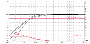
In this case, a situation arises as if the speaker was not installed in the housing at all, that is, the waves from the back side of the diffuser and from the front side meet in antiphase and largely eat each other up, as in a normal acoustic short circuit. That is why, below the tuning frequency, the bass reflex output drops twice as fast as that of a closed box. However, something else is worse - the diffuser no longer slows down anything, and the amplitude of its oscillations at very low frequencies begins to grow simply catastrophically. The subsonic filters found on some, usually thoroughbred, crossovers and amplifiers are made almost exclusively to counteract this bad habit bass reflexes. So, what exactly do we get by choosing a bass reflex as an acoustic design for our project? I want to warn you right away: calculating a bass reflex without computer programs designed for this is possible, and there are calculation formulas and nomograms for it. However, on the threshold of the third millennium, I cannot classify such methods as anything other than masochism. And I promised not to let formulas appear on the pages of this magazine, and so far I’m sticking to it. So for those interested, at the end of the article I place the address on the WWW, where there is an annotated selection of proven programs of varying degrees of complexity and sophistication. Here's a picture that explains (almost) everything. A 10-inch speaker was taken, its parameters suitable for installation in a bass reflex, and the characteristics that would be obtained when installed in the optimal bass reflex for it (20 l, tuned to 42 Hz) and a closed box of the same volume were simulated.
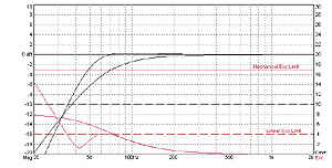
The upper of the two black curves is, of course, ours. Compared to a closed box, the response is significantly higher throughout the entire frequency band below about 150 Hz. What does "substantially" mean? Take a look: at a frequency of, say, 60 Hz, the difference is about 4 dB. And this is equivalent to increasing the amplifier power by 2.5 times. That is, with a modest 100-watt amplifier, such a sub will play as if 250 watts were supplied to it. For the same money. But of the red curves depicting the dependence of the amplitude of vibrations of the diffuser on frequency, ours is the lower one. Just where most of the bass energy is concentrated - below 100 Hz, the amplitude begins to drop and remains much lower than that of a closed box, although the sound pressure generated is twice as much! In a closed box, the amplitude of oscillations increases steadily and, when the power indicated as maximum is applied, it goes beyond the operating range (red dotted line) already at 70 Hz, and below that it’s a disaster. This is where the familiar wheezing sounds that accompany the bass notes will be generated. With a bass reflex, grace with amplitudes continues up to about 30 Hz, and there the amplitude begins to grow irrepressibly. However, there is almost no sound there, so the direct meaning is to “strangle” this part of the spectrum with a subtonal filter (if there is one) and enjoy impact efficiency with a minimum of distortion in the actual audio range. "Great!" - the impatient and decibel-hungry reader will exclaim, slam the magazine shut and immediately go to repair the holes in his own subwoofer. Comrade, stop! See what might happen next. Let us leave everything unchanged, take the old speaker out of our 20-liter box and install another one - designed to work specifically in a closed case.

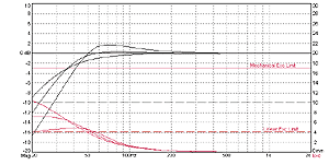
His performance in the closed, native box (lower on the graph) was very nice. And after converting it into a bass reflex, it will become like the top one, that is, it will give a pronounced “pop” between 50 and 100 Hz. It was as a result of the creation of such combinations that bass reflexes at one time received the offensive nickname boom-box (“booze”), which was later used, this time quite rightly, for some kind of portable radio. What was the difference between the two speakers? In two parameters that must be in a certain harmony for a given acoustic design, otherwise, everyone who sounds here, give up hope, so to speak. These parameters are the resonant frequency Fs and the total quality factor Qts. For the “closed” speaker they were Fs=25 Hz, Qts=0.4. And the “bass reflex” one has 30 Hz and 0.3. It seems that the difference is not so great, but the results differ significantly. The energy bandwidth parameter Fs/Qts, invented at one time, immediately shows who is who: its value for the first speaker is 62.5, and for the second - 100. The rule is simple: if Fs/Qts is noticeably less than 100, forget the word “bass reflex” . If it’s close or more, remember again, and forget about the closed box. In the region of 90 - 100 there is a “twilight zone”, where, with certain concessions, one or the other can be used. But what happens if you insist on your own and push the speaker into a design that is unusual for it? Let's try, fortunately while the drama is unfolding on paper and a computer screen, that is, “with little loss, on foreign territory.” To begin with, we put the “bass reflex speaker” in a closed box and try to vary the only parameter we have - the volume of this box.
There are three curves on the graph. The flattest is the result of installation in a box with a volume of 50 liters, the steepest drop below 100 Hz is the result of installation in a box with a volume of 10 liters. And in the middle is our original characteristic in a 20-liter volume. We see: the volume changes from indecently small to impractically large, but a good characteristic does not come out - it either begins to fall off too early, or falls off too quickly. A speaker designed for a closed box, as can be seen from the following graph, has the opportunity to either hit the optimum (middle curve), or “cut” on the volume, thereby obtaining a rather noticeably “buzzing” characteristic (the upper curve, plotted in volume 10 l).
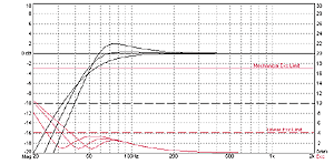
What about the other way around? When installing a “closed” speaker into a bass reflex, is it possible to configure it in such a way as to obtain an even frequency response? Theoretically, yes, fortunately, with a bass reflex, you can adjust the frequency at a constant volume by changing the diameter and length of the tunnel (in practice, always the length, of course). We start the experiment with the upper, absolutely terrible curve (volume 20 liters, tuning frequency 50 Hz) and, gradually rebuilding the bass reflex, suddenly at a tuning frequency of 20 Hz we notice that we have arrived at a very nice curve (lower on the graph).

Oops, let's now figure out which tunnel is needed for this - and go ahead! After half a second of computer time, we receive data that in order to tune a 20-liter volume to a frequency of 20 Hz, you need a tunnel with a diameter of 75 mm and a length of 1 m 65 cm. That is, the height of a miniature lady, and not the size of a compact subwoofer part. But a “bass reflex” speaker will allow you to adjust the frequency with minimal hassle (push in or out the pipe) no worse than using an equalizer. The graph shows the results of such activity in the tunnel tuning frequency range from 35 to 52 Hz, which required a tunnel length from 190 to 400 mm - God knows what, even at the highest value.
In the next part of the saga about subwoofers (of course, not the last - the topic is boundless, and God is merciful and, perhaps, will extend the years of the author), we will directly address the issue of the practical implementation of the plan - for those who want to do it themselves, or for those who want to be able to distinguish the work of a competent installer from the efforts of an ignorant hack. Agree, even when traveling in a taxi, it is useful to know that the path from Sokolniki to Izmailovo passes somehow away from Chertanovo... For those with access to the Internet, as promised, the coordinates of the rookery of subwoofer calculation programs. Search in the “Information Resources” section and, I promise, you will find it.
See you in the bass range...
I didn't vote either up or down. I can’t for reasons of lack of faith in the device. Against because
feelings of camaraderie. You can brand me with disgrace for the second.
I can say right away that I have not used or even assembled a resonant frequency generator (RFG). I don’t know how it works in practice. The reason is that at that time I already had a generator and a millivoltmeter, and after reading Golunchikov’s article I didn’t understand how the FI could be configured correctly using the GRF. And now I don’t understand. Familiar, but practically did not work.
Let's think about it and carefully read what is written in the articles:
V. Burundukov writes that with the help of this device You can quickly measure the resonant frequency of an acoustic unit. Okay, but how? We started the generator, it generated, so what? How can you determine this frequency? Aurally? Exactly how many hertz are there?
Can anyone answer?
He further writes that resonant frequencies are determined using appropriate measuring instruments. We've arrived. The resonant frequencies are already known. Most likely dynamics without a box. And we are most likely talking about comparing this and that. That is, the meaning of using the device is not completely clear.
As for setting up the FI, everything is clear; all the articles clearly state: lasing occurs at the resonance frequency of the loudspeaker in the corresponding volume. That is, it's not
The resonant frequency of the speaker in open space is the resonance of the system. We put the din in a large volume - resonance one, take a smaller volume, resonance another.
Right or wrong?
The times were long ago, few people knew about Thiel and Small, at least the mathematical calculation of FI was inaccessible. There were different methods, it doesn’t matter.
Speaker Golunchikova it is possible and can be adjusted acceptably, after all, the volume of the box is not small, and even filled to capacity with a sound absorber. that is, the resonance of the dyne in the box should increase slightly. Apparently the same applies to other large speakers.
Let's move on. We are asked to tune the FI to the resonant frequency of the speaker in the box.
Let be. Let Fs (resonance in free space), equal to about 30 Hz, become equal in the box to, well, 40 Hz. We denote the resonance in the box as Fc. In principle, it’s normal; by tuning the FI to this frequency, nothing nasty will happen. It will work, no question. Not entirely accurate, but if you also take into account the room and location of the speaker, everything is fine. The not-smooth theoretical frequency response is not scary; anyway, indoors it resembles mountains at low frequencies.
Now let's take another example and try to configure Saltykov's AS in the same way.
Volume about 9l. Din 6GD-6 or 10GD-34. The resonance (Fs) of these dins is about 80 Hz. Rare examples below. But rare. So, in a 9 liter box the resonance will go above 80 Hz.
I hope no one will argue with this? It is to this frequency that the FI is tuned when using this device. And it is necessary, as you remember, it is necessary (in my opinion) about 50-55Hz.
How do you like it?
Tell me what I'm doing wrong?
Now about the modern one. According to authoritative sources (Vinogradova and Aldoshina are quite authoritative, if not legendary), there is a total quality factor equal to 0.383
, in which the FI is tuned to the resonant frequency of the dyne in open space (not in a box). In this case, the volume of the box is taken to be 1.41 times less than the equivalent volume of the dyne.
That is, the flexibility of the air in the box is less than the corresponding dynamic parameter.
It is probably possible to calculate cases when the FI needs to be tuned to the resonance of the dyne in the box, I think these cases are combinations of unit parameters.
If the quality factor is greater than 0.383, then FI is always adjusted lower than Fs. Without fail.
By by and large FI will always work, the only exception being when it is set so low that FI becomes a closed box with a hole. But this is an unlikely case.
If the entire chain (amplifier, cable to the speakers, and speakers) is built normally, there may even be a hump
It won't hurt the frequency response. Maybe even the increased quality factor of the dyne is not a hindrance. If the other components (PA and cable) can cope with this, there is nothing wrong with the frequency response curve.
If, of course, the ear likes it. All the same, everywhere the final tuning of FI is done by ear.
Something like that. In my opinion, it turns out that the device is useless. Neither quickly measure nor adjust.
The method of calculating an acoustic bass reflex by Yu. Lyubimov based on materials from the magazine "EW" (P-7/68) is based on simple measurements carried out with a well-defined sample of a loudspeaker installed in an acoustic bass reflex and on a nomographic determination of the dimensions of the latter.
First of all, guided by Fig. 1 and the table, it is necessary to make a “standard volume” - a sealed plywood box, all the joints of which, in order to avoid air leaks, are carefully adjusted, glued and coated with plasticine. Next, the natural resonance frequency of the loudspeaker located in free space is measured. To do this, it is suspended in the air away from large objects (furniture, walls, ceiling).
| Diffuser diameter loudspeaker, mm |
Dimensions, mm | ||
| A | IN | WITH | |
| 200 | 255 | 220 | 170 |
| 250 | 360 | 220 | 220 |
| 300 | 360 | 220 | 270 |
| 375 | 510 | 220 | 335 |
The measurement diagram is shown in Fig. 2. Here ZG is a graduated sound generator, V is an alternating current lamp voltmeter and R is a resistor with a resistance of 100...1000 Ohms (at higher resistance values, the measurement is more accurate). By rotating the frequency adjustment knob of the sound generator in the range from 15...20 to 200...250 Hz, achieve the maximum deflection of the voltmeter needle. The frequency at which the deviation is maximum is the resonant frequency of the loudspeaker in free space FB.
The next stage is to determine the resonant frequency of the FYa loudspeaker when it is operating at a “standard volume”. To do this, the loudspeaker is placed with a diffuser on the hole of a “standard volume” and pressed lightly to avoid air leaks at the junction of the surfaces. The method for determining the resonance frequency is the same, but in this case it will be 2-4 times higher.
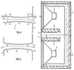
Knowing these two frequencies, the dimensions of the bass reflex are found using nomograms. Depending on the diameter of the loudspeaker cone, choose the nomogram shown in Fig. 3 (for a diameter of 200 mm), in Fig. 4 (for a diameter of 250 and 300 mm) or
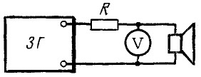
Fig.2
In Fig. 5 (for a diameter of 375 mm). Using the selected nomogram, the volume of the phase inverter is determined by connecting the points corresponding to the found frequencies with a straight line on the axes “Resonant frequency FB” (see Fig. 4, point A) and “Resonant frequency FYa” (point B). Mark the intersection point C with the auxiliary axis and from here draw a second straight line through point D to the “optimal volume” axis. The value corresponding to the new intersection point E is the required volume. If there are no special considerations for designing a box of a special configuration, then the calculation internal dimensions for a given volume it can be done according to the nomogram shown in Fig. 6. The width of the bass reflex will be equal to 1.4 times the height, and the height will be equal to 1.4 times the depth. Using the nomogram is not difficult: draw a straight line between the extreme axes on which the volume values are plotted. The intersection points of the straight line with the A, B, C axes will determine the width, height and depth of the box. The diameter of the cutout for the loudspeaker is equal to size C indicated in the table.
Next, having specified the diameter of the tunnel, you need to determine its length and check whether it fits into the bass reflex box. The length of the tunnel is found from the graphs shown in Fig. 7 for three internal diameters: graphs A - for a diameter of 50 mm, B - for a diameter of 75 mm, and B - for a diameter of 120 mm. By selecting the appropriate graphs, by frequency
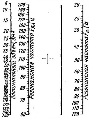
Fig.3
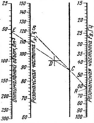
Fig.4
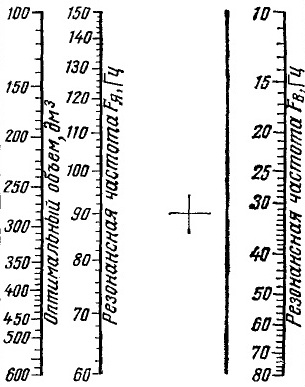
Fig.5
FB and the volume of the bass reflex, determined earlier, find the length of the tunnel (example in Fig. 7B). It should be 35-40 mm less than the internal depth of the box. If this does not work, you can slightly change the configuration of the box, maintaining its volume, or take a different tunnel diameter.
The bass reflex is made of plywood about 20 mm thick. If there is no such thick plywood, then to increase rigidity you need to glue bars measuring 25 x 75 mm diagonally or crosswise inside the box. The box is assembled with screws and glue and all seams are sealed. Rear wall It is recommended to fasten with screws (five pieces on one side) with a felt pad. The tunnel is made from thick-walled cardboard tube.
Having made a bass reflex and installed a loudspeaker in it, we begin to dampen it. To do this, it is recommended to completely cover the loudspeaker from the back with a layer of glass wool 25-50 mm thick, attaching it to the board around the diffuser holder using a ring screwed with screws or screws. The sufficiency of damping is checked using the diagram shown in Fig. 8. The resistance of resistor R is taken to be about 0.5 Ohm. If the damping coefficient K of the amplifier with which the unit will work is known, and the resistance voice coil loudspeaker alternating current r, then it can be determined from the formula R = r/K, Ohm.
When moving the switch from one position to another, listen for a click in
The logical ending to the saga of the bass reflex will be the practical aspects of its implementation. The key element here is the pipe, which is also a tunnel, which, as a result of slavish transliteration from English, is also a port. It is this, the pipe, that will make it possible to implement in practice two main parameters that determine the acoustic appearance of the conceived bass reflex: the volume of the housing and its tuning frequency. These two values, one in liters, the second in hertz, are the result of either an independent calculation or following previously made calculations. Their source may be the speaker manufacturers, our tests, or expert advice based on their practice. In all three cases, it happens that ready-made tunnel dimensions are given, ensuring the tuning of a known volume to the desired frequency, but, firstly, not every time, and secondly, blind copying is not always possible and is always not commendable. So the following formulation of the problem will be more general and much more productive: the volume and frequency are known, and we will solve the question of their physical, material, implementation on our own. Part of the story will be organized according to the principle of questions and answers: the nomenclature of questions is known, in the editorial mail they are repeated with regularity, giving rise to statistical calculations that our testing department loves so much. I won’t take away their favorite toy, or ours. So, what first, do we calculate the tunnel or buy the pipe that will become this tunnel? In theory, you need to buy it first - pipes do not come in any diameter, but from a certain range of values, if you take ready-made ones, and do not wind them yourself from paper with glue, like a pioneer from a young cosmonaut's circle. But you still have to start with at least a rough estimate, and the point here is that...
Thickness matters
If the tunnel is really a pipe (there are options, after all), what diameter should it be? The most general and crudest answer is: the more, the better. The advice is really radical and can cause a protest reaction: what if I take and make a tunnel with a diameter twice the size of the speaker? You won’t take it and won’t do it, no matter how hard you try, this was taken care of more than a hundred years ago by a certain Hermann Helmholtz, whose resonator name the bass reflex is, and later by the creators of cars, who made them smaller in size than the steam locomotives that existed at that time. So, in order, why more and why something will stop this process.
During operation near the tuning frequency, where, in fact, the bass reflex tunnel performs its functions, adding to the sound waves generated by the vibrations of the diffuser, air moves inside the tunnel. It moves oscillatingly, back and forth. The volume of moving air is exactly the same as that driven by the diffuser during each oscillation; it is equal to the product of the diffuser area and its stroke. For a tunnel, this volume is the product of the cross-sectional area and the air flow inside the tunnel. The cross-sectional area is always real less area diffuser (if anyone has not yet given up the threat to make the same, or even more, they will soon not go anywhere and refuse), and in order to move the same volume, the air needs to move faster, the speed in the tunnel with a decrease in diameter increases in proportion to the decrease in its area sections. Why is this bad? Everyone at once. First of all, the Helmholtz resonator model, on which everything is based, assumes that there is no energy loss due to air friction against the tunnel walls. This, of course, is an ideal case, but the further we move away from it, the less work bass reflex will resemble what we expect from it. And the higher the air speed inside the tunnel, the higher the friction losses in the tunnel. Theoretically, the formula, and even the simple program based on it, does not take these losses into account and will meekly give you the estimated length of the tunnel with a diameter of even a finger, but such a bass reflex will not work, everything will die in the turbulence of the air trying to quickly fly backwards through the tight tunnel. forward. The text of a traffic police propaganda poster I once saw, “Speed is death,” certainly applies to the movement of air in a tunnel, if death is attributed to the effectiveness of the bass reflex.
However, much earlier than the phasic dies as a means of sound reproduction, it will become a source of sounds for which it is not intended, vortices that arise from excessive high speed air movements will create jet noises that disrupt the harmony of bass sounds in the most shameless and unaesthetic way.
What should be taken as the minimum cross-sectional area of the tunnel? You will find different recommendations in different sources, not all of them have ever been tested by the authors, even through a computational experiment, let alone others. As a rule, such recommendations include two values: the diameter of the diffuser and the maximum value of its stroke, that is, Xmax. This is reasonable and logical, but it fully applies only to the operation of the subwoofer at the maximum mode, when it is already a little late to talk about sound quality. Based on numerous practical observations, you can adopt a much simpler rule; it is not perfect and not entirely universal, but it works: for an 8-inch head, the tunnel must be at least 5 cm in diameter, for a 10-inch -
7 cm, for 12 and more - 10 cm. Is it possible to have more? It’s even necessary, but right now something will stop us. Namely, the length of the tunnel. The fact is that...
Length matters
As was said, she will be commanded by the great Hermann von Helmholtz. Here he is, at the blackboard at the University of Heidelberg, and on the blackboard is the same formula. Well, okay, this time I wrote it, but I made it up - he would have written it exactly the same way. This simple dependence, since it was derived for the ideal case, shows what the resonance frequency of a certain cavity will be (we are more familiar with a box, although Hermann von made some kind of bubbles with pipe tails) depending on the volume V, length L and cross-sectional area of the tail. Please note: there are no speaker options here, and it would be strange if there were. In any case, it is useful to remember and never succumb to provocations: the bass reflex setting is completely and exhaustively determined by the size of the box and the characteristics of the tunnel connecting this box with environment. In addition, the formula includes only the speed of sound in the atmosphere of planet Earth, designated “c,” and the number “pi,” which does not even depend on the planet.
For practical purposes, namely, calculating the length of the tunnel using known data, the formula can be easily transformed by remembering your native school, and the constants can be substituted in the form of numbers. Many people did this. Many people published the results of this exciting process, and the author is a little surprised how it was possible to screw up spectacularly during an operation with three or four numbers. In general, a third of the converted formulas published on paper and on the Internet are incomprehensibly nonsense. The correct one is given here if you substitute the values in the units shown in black.
The same formula, plus some corrections, is included in all known programs for calculating bass reflexes, but right now the formula is more convenient for us, everything is in sight. Look: what will happen if, instead of the minimalist tunnel, we install another, larger (and therefore better) one? The required length will increase in proportion to the square of the diameter (or in proportion to the area, but we were going to buy a pipe by diameter, they don’t sell it any other way). We switched from a 5-centimeter pipe to a 7-centimeter one, for example, the length with the same setting will need twice as much. We moved to 10 cm - four times. Trouble? So far - not so bad. The fact is that...
Caliber matters
There will be trouble now. Let's look at the formula again, this time - at the denominator, focus your vision. All other things being equal, the length of the tunnel will be greater, the smaller the volume of the box. If in order to tune a 100-liter volume to 30 Hz, having at your disposal a 100 mm plumbing pipe, you need to open and paste a 25-centimeter-long piece of shit pipe into the box, then with a box volume of 50 liters it will be half a meter (which is no less than half the problem), and with the fairly common 25 liters, a tunnel of such thickness will have to be a meter long. This is already a disaster, there are no options.
In our practical conditions, the volume of the box is primarily determined by the parameters of the speaker, and for reasons already well known to readers of this series, for 8-inch heads the optimal volume rarely exceeds 20 liters, for “tens” - 30 - 40, only when it comes to reaches 12-inch caliber, we begin to deal with volumes of the order of 50 - 60 liters, and even then not always.
So we get some kind of parade of sovereignties: the tuning frequency of the FI is determined by the bass that we want to get from it, whether it’s on the “eight” or on the “fifteen” - it doesn’t matter. And the tuning frequency of the box again does not depend on the speaker; the smaller the volume, the longer the tunnel. The result of the parade: as we have repeatedly noticed in tests of small-caliber subwoofers, the desired and promising design option in FI is physically impossible (or difficult) to implement. Even if you don’t mind the space in the trunk, you cannot make the volume of the FI box larger than the optimal one, and the optimal one often turns out to be so small that setting it to a frequency of 30 - 40 Hz, which is invariant to other factors, is unthinkable. Here is an example from a recent test of 10-inch subwoofer heads (“A3” No. 11/2006): if we take a pipe diameter of 7 cm as an axiom, then in order to make a bass reflex on the Boston head, a piece of it 50 cm long would be needed, for Rainbow - 70 cm, and for Rockford Fosgate and Lightning Audio - about a meter. Compare with the recommendations in the test of this issue relating to 15-inch heads: none of these problems were noted. Why? Not because of the speaker, as such, but because of the initial volume selected according to the speaker parameters. What to do? Meet adversity head-on. Generations of specialists (and others) forged our weapons. Do you know what's the matter?
Shape matters
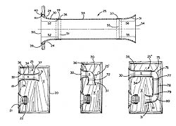
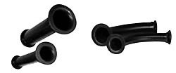
You could hardly fail to notice: I really like delving into patents, because I believe that the road from invention to real life is not so short, a patent is a reflection of a thought in the form of a vector, that is, taking into account the direction. Most of the innovations proposed (and steadily proposed) by tireless minds in relation to the bass reflex are concentrated on combating two interfering factors: the length of the tunnel, when its cross-section is large, and jet noise, when they tried to reduce its cross-section, trying to reduce the length. The first, simplest solution, the admissibility of which we are asked in our editorial mail about five times a month: is it possible to place the tunnel not inside the box, but outside? Here is the answer, final, factual and real, like a paper for Professor Preobrazhensky’s apartment: you can. At least partially, at least entirely, the tunnel was pushed inside the box solely for aesthetic reasons; von Helmholtz had it sticking out outside, and nothing, he survived it. And our modern times provide examples: for example, car audio veterans cannot help but remember (many, frankly speaking, cannot forget) the “bass pipes” of the SAS Bazooka company. They started with a patent for a subwoofer that could be conveniently placed behind the seat of a truck, America's favorite vehicle. To do this, the inventor stretched the bass reflex pipe along the body from the outside, at the same time giving it a shape spread out over the surface of the cylindrical body. This is one example, there is another: some companies that produce built-in subwoofers for home theaters bring out a pipe-tunnel of a bandpass subwoofer. Subwoofer type in this case doesn’t matter: it’s the same resonator of the name you know who. Judging by the letters, they are also looking for another solution, but they are afraid. “Is it possible to bend a tunnel?” The answer is in the style of Philip Philipovich and is obvious. Otherwise, several companies (DLS, JL Audio, Autoleads, etc. etc.) would not have released it at once. flexible pipes specifically for this purpose. And in the field of patent documentation there is even an interesting hint on how this problem can be solved not without grace and material savings: at one time a design was proposed for a model tunnel that would be assembled from standard elements in any desired form; the illustration will tell the rest. I’ll add on my own behalf: most of the details depicted in the patent are touchingly reminiscent of the nomenclature of elements of local sewer networks, which is a practical recipe for introducing the intellectual excess of the American inventor.
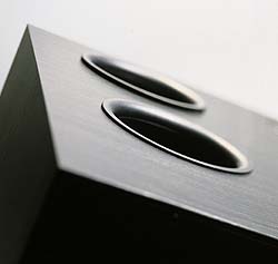
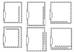
When struggling with the inappropriate length of the tunnel, they often take the path of constructing so-called “slot ports”, their advantage lies in their constructive integration with the body, which allows, with a certain imagination, to make the tunnel quite long; in the attached diagram there are several options at once, which the question is, Of course, it is far from being exhausted (the three top sketches belong to the pen of the famous high-end designer Alexander Klyachin, the rest was a matter of technique).
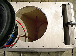
The disadvantage of the slots is that it is difficult to adjust the length, this is not plumbing PVC - waved the saw, and that was it. But there are solutions here too: not so long ago, one of the heroes of the “Own Game” column, Permian Alexander Sultanbekov (it’s not a sin to once again remind the country of the names of its heroes) demonstrated in practice how a slot port can be adjusted by changing its cross-section while maintaining a constant length, he I did it by placing plywood spacers inside, as shown in the photo somewhere nearby, look for it.
In folding the bass reflex tunnel, some bright minds went to extremes: one bright one suggested, for example, folding the tunnel in the form of a spiral around a cylindrical loudspeaker body, another responded to Helmholtz’s cunning formula with a screw tunnel, this concept is familiar to us here in Russia...
But in general, all these solutions (even with a propeller) are frontal; here a tunnel of constant length is simply attached or folded so that it does not interfere. Implementations of another principle are known (and even sold in commercial quantities). Here's the thing.
Section matters
Not the area as such, but the nature of its change along the length of the tunnel. Until now, we, guided by the teachings of von Helmholtz in its simplest, school form, have considered it indispensable that the cross-section of the tunnel is constant. But there were people who violated this condition and even made money from it.
Experienced readers remember, for example, the article by our Italian colleague Professor Matarazzi, where he suggests effective solutions to reduce the length of the tunnel by giving it a conical or double conical, hourglass shape. In “A3” No. 10/2001, calculations for the professor’s programs are presented in the form of tables, and the sir recently found and sent the programs themselves, at our request. By the time this issue comes out of print, we will post them on the website in the “Appendices” section. True, the absent-minded professor lost the source code forever, so the programs remain in Italian, if anyone knows how to translate without having the code, we will accept help with gratitude.
For now, let us note: the professor is neither the first nor the only one in his research. Even tragedies occurred in this direction. Long-time readers of the magazine may remember the article in “A3” No. 2/2003 about a lawsuit regarding a bass reflex tunnel; let me remind you not so long ago: the Bose corporation noticed that another corporation, JBL, had used bass reflex tunnels with a curved generatrix in its speakers, called Linear-A has seriously infringed the intellectual property of Bose Corp. As evidence, a US patent was cited, which mentioned, among other things, that it would be nice to make the tunnel with an elliptical generatrix; then it would be shorter and quieter in terms of jet noise. In vain, JBL tried to explain to the court that Bose has an ellipse, and JBL has an exponential one. The court explained that ellipses-schmellipses are a minor matter, and they sold a lot of speakers; Bose’s accounting department calculated: JBL’s profit amounted to 5,676,718 dollars and 32 cents, which was proposed to be deposited into the cash register of the offended party. They brought it in like nice little ones, including coppers, and in all the columns the tunnels were changed to others, FreeFlow, like an improved model. This is how it happens...
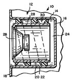
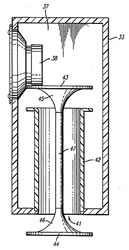
Many, many people have proposed moving away from the cylinder as a form of tunnel. Some - in the style of Matarazzi with variations, others - on a modest, local scale, limiting themselves to giving curved contours to the ends of the cylindrical tunnel in order to reduce jet noise from turbulence. The most radical means of combating both length and noise was not only invented, but also exclusively used for many years by Matthew Polk, the founder of a company named after him. The essence of the device called PowerPort is this: part of the functions of the tunnel is taken over by one or two, at each end of the pipe, an annular slot between the wall of the box and a “fungus” placed at a strictly calculated distance from it, however, everything is visible in the figure. Almost all Polk Audio home speakers are equipped with such tunnels. And if someone encroaches, they pay him 32 cents plus something else. For yourself, your loved ones, no one will forbid you to try such a thing, especially since once upon a time Polk posted a table in Excel on his corporate website, according to which you can calculate everything, I then downloaded it from this site (having received later, in hindsight, the author’s blessing - I’m not doing it for profit) and even translated the accompanying instructions into the great and mighty one, it’s all on our website.
A propos, both the works of Professor Matarazzi and the revolutionary development of Matthew Polk remind us of this: Helmholtz’s gymnasium formula, among other things, does not take into account an effect that is very significant for practice: in the vast majority of cases (almost always) one of the ends of the tunnel is adjacent to the wall subwoofer enclosure, this applies to both round pipes, sawn off flush with the wall, and pipes equipped with an aerodynamic ending, and, to an even greater extent, slotted ports attached to the wall. The proximity of the wall creates an end effect reminiscent of what the author of PowerPort intentionally sought - a virtual extension of the tunnel. That is why modern applied specialists recommend introducing an amendment to the formula directly derived from the works of von Helmholtz, which is purely empirical, but no less necessary; it is highlighted in red so that it is clear where is the classic of the 19th century and where is the practice of the 20th.
But actually, dear friends, it’s time to get down to business, it’s not an age to dig through paperwork. This is exactly the point...
On the issue of thickness: pushing the same volume of air through a tighter tunnel, it will have to be accelerated to a higher speed. And “speed is death”

Helmholtz would have written his formula in exactly the same way, but there was no photographer at that moment
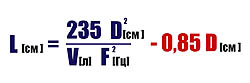
The final and actual formula replacing computer program. It is correct, it has been checked several times. The meaning of the “tail” highlighted in red will be explained in the text

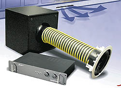
Could the tunnel be outside the box? Yes, a whole company built its business on this, the patent for an easy-to-place subwoofer was replicated by thousands of SAS Bazooka bass tubes. And manufacturers of built-in subwoofers for home theaters don’t give a damn...
Is it possible to leave the tunnel inside, but bend it as it is more convenient? Here's your answer

Exotic, desperate solutions: roll up the tunnel with a spiral or screw
The slot tunnel is integrated with the box, which makes it possible to make it longer than the usual “plug-in” one; adjusting the length, however, is much more difficult...
This means that it is not the length that needs to be adjusted, but the cross-section: this is how one resident of the capital did it Perm region

A move away from the cylindrical shape of the tunnel was proposed both to reduce its length and in the form of local “aerodynamic treatment” to reduce jet noise
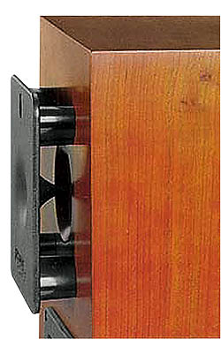
The most impressive solution in this area: Matthew Polk's PowerPort. The invention did not remain on paper, it is component almost all Polk Audio acoustics
Prepared based on materials from the magazine "Avtozvuk", February 2007.www.avtozvuk.com