The mooring device is designed to fasten the vessel to the berth, mooring barrels and bollards or to the side of another vessel. The structure of the device includes mooring cables, bollards, hawses, - bale strips, guide rollers, views, mooring mechanisms, as well as auxiliary devices - stoppers, throwing ends, fenders, mooring shackles.
Mooring cables (mooring lines) can be steel, vegetable and synthetic. The number of mooring cables on a ship, their length and thickness are determined by the Register Rules.
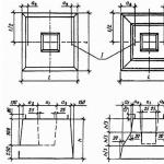
The main mooring cables (Figure 6.1) are fed from the bow and stern ends of the vessel in certain directions, excluding the movement of the vessel along the berth and departure from it. Depending on these directions, the mooring lines got their names. The cables fed from the bow and stern ends keep the vessel from moving along the berth and run up, respectively, bow / and stern 2 longitudinal. The cable, the direction of which is opposite to its longitudinal end, is called a spring. Bow 3 and stern 4 springs are used for the same purposes as the longitudinal ones. Cables fed in a direction perpendicular to the berth are called bow 5 and stern 6 clamping. They prevent the vessel from moving away from the berth during the squeezing wind.
Figure 6.1 - Mooring cables
Bollards - cast or welded bollards (steel and cast iron) for fastening mooring cables. On transport ships, paired bollards are usually installed with two bollards on a common base, which have lugs to hold the lower cable hoses, and hats that do not allow the upper hoses to jump off the bollards (Figure 6.2, a) They also install bollards with bollards without tides (Figure 6.2, b ) and bollards with a cross (Figure 6.2, c). The latter are convenient for fastening mooring cables directed from above at an angle to the deck. The bollards are installed in the bow and stern parts of the vessel, as well as on the upper deck on both sides symmetrically.
Sometimes single-bollard bollards - bitengs (Figure 6.2, d) are installed on transport ships, which are used for towing. Bitengs are massive pedestals, the bases of which are attached to the upper deck or passed through it and attached to one of the lower decks. To better hold the cable on the bits, there are spreaders.
Very convenient for mooring operations are bollards with bollards rotating in bearings, equipped with a locking device (Figure 6.2 -, e). The mooring lines fixed on the pier are placed with a “figure of eight” with two or three hoses on the bollards, and then on the windlass crank. When the cable is selected, the bollards rotate and freely pass the cable. At the right moment, they remove the cable from the turret and put additional hoses on the bollards. At the same time, the locking device keeps the cabinets from rotating.
Clues - devices through which mooring cables are passed from the vessel. They are steel (cast iron) castings with round (Figure 6.3, a) or oval (Figure 6.3, b) holes, bordering the same holes in the ship's bulwark. The working surface of the fairleads has smooth roundings, excluding sharp bends of the mooring cables. For mooring to the side of the vessel of small floating craft, hawses with tides - horns are used (Figure 6.3, c). For the same purpose, in the immediate vicinity of the hawse, ducks are welded to the bulwark or to its racks. In places where a railing is made instead of a bulwark, special hawses are fixed on the deck at the edge of the side (Figure 6.3, d). To supply mooring lines, towing hawses are used, firmly fixed on the bow and on the stern of the vessel, intended mainly for winding tow ropes. The strong friction of the mooring lines on the working surfaces of the fairleads of these structures leads to rapid wear of the cables, especially synthetic ones, therefore universal (Figure 6.3,) and rotary universal (Figure 46, e) hawses are widely used on ships. The universal hawse has vertical and horizontal rollers freely rotating in bearings, forming a gap into which the cable supplied to the shore is passed. Rotation of one of the rollers when the cable is pulled from any direction significantly reduces friction. The swivel universal fairlead has a cage rotating on ball bearings in the body

Figure 6.2 - Knights
Kip laths have the same purpose as mooring clews. By design, they are simple (Figure 6.4, a), with biting (Figure 6.4, b), with one (Figure 6.4, c) or several - two (Figure 6.4, d), three (Figure 6.4, e) - rollers. For wiring mooring lines supplied to high berths and ships with high sides, closed bale strips are used (Figure 6.4, f). The most widespread are bale straps with rollers, the use of which significantly reduces the effort required to overcome the friction forces that occur during the rope pulling.

Figure 6.3 - Keys
To guide the mooring cables from the fairleads to the drums of the mooring mechanisms, metal bollards with guide rollers are installed on the deck of the forecastle and poop.
Views are designed to store mooring cables. They have locking devices. They are installed in the bow and stern of the vessel not too far from the bollards.
Mooring mechanisms are used to pull the vessel on the established mooring lines to the berth, side of another vessel, mooring barrel, to pull the vessel along the berth, as well as to automatically control the tension of the mooring cables in case of water level fluctuations due to tidal phenomena or when the draft of the vessel changes during cargo operations.
Ship mooring mechanisms are: windlass, anchor-mooring and mooring capstans, anchor-mooring winches, simple and automatic mooring winches.
Windlasses and anchor-mooring capstans have drums (turochki), which are used to select mooring cables. On ships that do not have a stern anchor device, a mooring capstan is installed at the stern, which does not have a chain drum. The vertical position of the axis of rotation of the mooring drum of the capstan allows you to select mooring lines from any direction. The concave outer surface of the drum can be smooth or have vertical welps - rounded ribs. Welps prevent the cable from sliding along the drum, however, due to kinks on them, the cable is damaged faster. Therefore, with the widespread use of synthetic ropes on ships subject to high abrasion on rough surfaces, it is preferable to have capstans with smooth drums.
Anchor-mooring winches, installed on some ships instead of windlasses, are used in mooring operations in the same way as windlasses.
A simple mooring winch (fig. 48) has an electric motor / with a built-in disc brake. The rotation of the engine through the worm gear 2 is transmitted to the intermediate shaft, on which the gear 3 of the open cylindrical gear and the friction clutch 4 are mounted. The friction clutch is turned on and off by a manual drive 6. The mooring cable 8 is laid on the drum in even rows by a cable layer 7
An automatic mooring winch (Figure 6.5) compares favorably with a simple one in that it can operate in manual and automatic modes. In manual mode, the winch is used to pull the ship to the berth and to retrieve the given cables.
After the mooring cable is tightened when pulling the vessel, it remains on the drum, and the winch is switched to automatic mode, for which the necessary mooring line tension force is set on the machine. If, for any reason, the load on the cable deviates from the established one, the winch automatically picks up or straightens the mooring cable, providing a constantly set tension.
The length of the mooring cable that the winch can automatically release when the load exceeds the set limit is limited. In this case, the largest possible changes in the position of the vessel relative to the berth are taken into account. If, for example, with a strong squeezing wind, the cable tension exceeds the value set on the machine, then the winch releases the specified cable length, after which the machine will brake the drum and the winch will turn on a light or sound signal indicating an emergency mode of its operation. When choosing the limit of permissible length mooring line being bled, it is recommended to install the alarm in such a way that the signal turns on already at the moment when the first full row of line remains on the drum. Such an installation will give time to eliminate the danger of a complete bleed of the mooring line.
 Automatic winches are made in two versions: with a mooring turret connected to the mooring "drum by an uncoupling clutch, and without a turret. The latter are installed near the windlass and capstan.
1- electric motor; 2-reducer; 3-Turkish; 4 - cable tension indicator; 5 mooring drum; 6-manual drive of a tape stopper; 7-lever control uncoupling clutch; 8-rotating roller guide rack; 9-guide rack; 10- steering wheel of the engine ventilation unit.
The stoppers serve to hold the mooring cables when they are transferred from the drum of the mooring mechanism to the bollards. They are chain, vegetable and synthetic. The chain stopper is a piece of a rigging chain with a diameter of 10 mm, a length of 2-4 m, with a long link for fastening with a bracket to the deck butt at one end and a plant cable with a length of at least 1.5 m at the other. The stopper for vegetable and synthetic cables is made of the same material as the cable, but half the thickness.
Throwing lines are necessary for supplying mooring cables to the shore when the vessel approaches the berth. The throwing end is a vegetable line or a braided nylon cord 25 mm thick, 30-40 m long, with small lights embedded at the ends. One of them serves to fasten lightness - a small canvas bag tightly filled with sand and braided with shkimushgar, the other - for the convenience of using the throwing end.
Fenders are designed to protect the ship's hull from damage during mooring, parking at the berth or side of another vessel. They are soft and hard.
Soft fenders are canvas bags tightly stuffed with elastic, non-deformable material (for example, cork chips) and braided with strands of plant cable. The fender has a yoke with a thimble for fastening a vegetable cable to it, the length of which should be sufficient for fastening the fender overboard at low berths and the smallest draft.
Rigid fenders - wooden bars suspended on cables to the side of the ship. To give such a fender elasticity, it is rounded along the entire length with an old vegetable cable.
Mooring shackles are used to fasten the mooring cable to the coastal eye or the eye of the mooring barrel.
Fenders are designed to protect the ship's hull from damage when mooring to coastal facilities or other vessels. As such means, wooden, metal, rubber-metal and rubber fenders are used.
Wooden fenders are made mainly from pine, cedar and larch, less often from oak and ash. By design, they are divided into single-row and double-row, and their dimensions are taken depending on the displacement of the vessel.
Due to the elastic properties, the tree absorbs the impact energy well, being the first to collapse when the CS is piled onto a solid wall. The disadvantage of wooden fenders is a short service life, frequent replacement of the beam.
metal fenders do not have a shock-absorbing capacity, the impact of the vessel on the berth is not softened, but is distributed over a large length of the hull. They are made from steel standard pipes from the same steel as the COP.
The rubber-metal fender effectively absorbs the impact energy and at the same time ensures the load distribution on the side of the compressor station. However, it is much more expensive, difficult to manufacture and requires more careful monitoring during operation. For these reasons, such fenders have found application only on railway ferries and on large crane ships, often moored, for which impacts on the pier during mooring are especially dangerous.
Rubber fenders are increasingly used in domestic and foreign shipbuilding. rubber fenders type SD, supplied by the Dutch company Vredestein. They have good energy-absorbing ability, resistance to atmospheric precipitation, simple design and fastening to the body. However, they contribute much less to the distribution of the load on the hull than all other types of fenders.
All fenders are installed at or near the decks, side stringers or longitudinal framing, which ensures better distribution of the load on adjacent frames and other elements of the pressure hull
6.2 Main types of mooring lines
The main types of mooring ropes (cables) and their characteristics.
Depending on the type of vessel and the conditions of its mooring, the following types of mooring ropes (cables) are used in shipbuilding practice:
steel;
Vegetable:
a) hemp;
b) manila;
c) sisal;
Synthetic.
On tankers carrying goods of the 1st and 2nd categories, steel cables are prohibited for mooring for fire reasons. On ships carrying flammable oil products and tropical navigation ships, vegetable and synthetic ropes are mandatory.
Steel ropes (cables). The design of steel ropes is characterized by the following main elements:
The number of strands;
Number of wires in strands;
Type and number of cores;
lay direction;
The nature of the touch of the wires in the strands;
Type and type of lay.
Among steel ropes, the most common are six-strand ropes with organic cores, which are easily spliced due to the rational ratio of the diameters of the strands and the central core. Organic cores in each strand and in the center of the rope, made of hemp, manila or cotton, give the ropes elasticity and, consequently, greater resistance to dynamic loads. In addition, lubricated organic cores fill the gaps between the wires and protect them from moisture.
Depending on the direction of laying the strands, the cables can be right-handed or left-handed. For mooring ropes wound on the turrets from any side, it is more expedient to use the cables of the right lay. The direction of the lay is chosen in such a way that, when winding on the drum, the rope must be additionally twisted, providing the specified lay density and durability.
According to the nature of the touch of the wires in the strands, ropes with a linear touch (L K) and a point touch (TK) of the wires are distinguished.
Ropes LK have increased resistance to wear, as they are made of wires of different diameters, which ensures a high density of their lay, so they work reliably on mooring winches. However, TK ropes are more resistant in hard working conditions.
According to the type of lay, ropes are distinguished:
One-sided lay, in which the directions of the lay of wires in strands and strands in ropes coincide;
Cross lay, in which the directions of the lay of the strands and the rope are opposite, the ropes of this lay have a greater structural strength and therefore are more often used for mooring lines, despite the increased rigidity.
According to the type of lay, the ropes can be:
Ordinary;
Non-twisting.
In ordinary ropes, the wires and strands are not freed from internal stresses that appear during the laying process and tend to unwind the rope.
In non-twisting ropes, the wires and strands are given spatial curvature before laying by preliminary deformation of the wires and strands and thereby relieving internal stresses. In addition, these ropes are most widely used due to their advantages:
Have more flexibility;
They do not twist when the rope is pulled onto the drum;
They differ in a more uniform distribution of tensile forces on each strand, and inside the strand - on each wire;
Provide greater resistance to fatigue stresses caused by variable bending;
When broken, they do not unravel; individual broken wires retain their position in the rope, which greatly facilitates manual work with it and protects the surface of the drums and drums from damage.
Regardless of the design, steel cables are classified:
According to the tensile strength of the wire material;
According to the viscosity of the wire;
For anti-corrosion protection, which must be specified when ordering.
The tensile strength of the rope wire ranges from 70-210 kg/mm 2 . When ordering cables, it should be taken into account that the standard parts of mooring devices are designed for the breaking load of a steel cable with a wire tensile strength of 140-150 kg / mm 2, and mooring mechanisms, according to current standards, are designed to work with steel cables with a wire tensile strength of 160 kg / mm 2 - with a cable diameter of up to 33.5 mm and 140 kg / mm 2 - with cables of a larger diameter. Based on this, the strength of steel cables for mooring ships should not be higher than that for which the details and mechanisms of mooring devices are designed.
The viscosity of the wire is an important indicator of the quality of the rope, on which the number of variable bends and twists depends.
when testing the rope for endurance. According to this indicator, the ropes are divided into:
Ropes of the highest grade;
Ropes brand I;
Ropes grade II.
The increased viscous properties of the wire extend the life of the mooring ropes, so they are usually used for the manufacture of grade I cables.
According to the nature of anti-corrosion protection, the ropes are distinguished depending on the size of the zinc coating of the wires: LS, SS and ZhS. For moorings, ropes with zinc coating ZhS are used; CC coverage is allowed as an exception.
For ordinary mooring ropes that do not work on automatic mooring winches, it is advisable to use steel cables of the TK type, having 6 x 24 = 144 wires with seven organic cores.
In the practice of domestic navigation, the following steel ropes are most widely used:
Type TK, consisting of 6 x 24 = 144 wires and 7 organic cores;
Type TK, consisting of 6 x 37 = 222 wires and one organic core;
Type LK-RO, containing 6 x 36 = 216 wires and one organic core with wire strength limits of 150 and 160 kg / mm 2 (to reduce the size of winch drums);
Type I with ZhS anti-corrosion coating, right lay with wire strength of 140 and 150 kg/mm 2 , for which standardized products of mooring devices (winch drums, bollards) are designed.
In automatic mooring winches, a steel six-strand cable of the TK and LK types can be used.
Hemp ropes are made of two types: white and pitch, that is, impregnated with hot wood resin. Three-strand hemp ropes (cable work), right lay, elevated and special are most often used as mooring lines. The main advantage of all vegetable ropes is their high elasticity.
The disadvantages of hemp ropes include:
Great weight;
Ability to get wet and loss of flexibility;
Tendency to rapid decay and loss of strength;
susceptibility to harmful bacteria;
Contamination of the ship and sailors' overalls with tar.
Manila ropes are made from manila yarn (kabolok), obtained from the fibers of the leaves of a perennial abaca plant growing in the Philippine Islands. The domestic industry produces ordinary three-strand manila ropes for shipbuilding.
A valuable property of manila ropes is that they do not need to be tarred, as they are not impregnated with moisture, do not rot and retain their weight when exposed to moisture. For mooring lines, manila ropes of normal strength are used.
Sisal ropes are made from sisal yarn (kabolok), obtained from the fibers of the leaves of the agave-steel, growing in tropical countries. In appearance, they resemble Manila, but are inferior to them in strength and moisture resistance.
Manila and sisal ropes are stronger, lighter and more flexible. Man-made fiber ropes are made from thin threads of capron, nylon or perlon. The domestic industry produces three-strand, right lay nylon ropes with a circumference of up to 200 mm, the mechanical and weight qualities of which are regulated by GOST 10293-62.
Experience shows that in most cases the use of artificial fiber ropes as mooring lines does not entail significant structural changes in the details of the mooring device.
Nylon ropes have the following operational advantages:
They are more than 5 times lighter than hemp ropes and about 2 times lighter than steel ropes with the same breaking force;
They do not absorb water, do not swell in water, do not lose flexibility, like hemp ropes;
They cannot be damaged by mold, marine bacteria, they can be stored immediately after being in the water;
Due to their high elasticity, they are very resistant to dynamic loads, which allows them to be successfully used for mooring in waves;
When working on mooring drums, they receive little wear and almost no fraying.
Due to their lower weight compared to vegetable ropes, nylon ropes are preferred for mooring devices with conventional mechanisms, i.e. in the case of manual labor during mooring operations.
Flaws kapron ropes:
Less coefficient of friction when working on the mooring drum, which requires an increased number of hoses and an increase in the number of people to select the running end of the rope;
Increased elongation, accompanied by residual deformation, which adversely affects the use of a nylon rope when using mooring winches with a permanent fastening of the rope on the drum;
The need for more thorough processing of the working surfaces of mooring drums (turets), as well as bollards, than is required when working with ropes of other types;
Greater sensitivity to an increase in the load acting on the rope in excess of the nominal; in addition to an increase in residual deformation, there is a violation of the smooth sliding of the cable hoses along the drum, which is expressed in the appearance of jerks;
Higher heating of the mooring drum than when working with ropes of other types;
The need for increased precautions when working together with the capstan, windlass and winch, since when the vessel is pulled up, the rope is strongly stretched and turns into a kind of spring;
In the event of an accidental loosening of the end of the rope running off the mooring drum, an instantaneous rebound of the rope in the opposite direction, dangerous for workers, can occur.
In practice, six-strand ropes of the "Hercules" type are used, which are made from special combined strands, consisting of plant cables and galvanized steel wires. Since the rope strands contain steel wires with a tensile strength of 140 kg / mm 2, their strength is 2 times greater than the strength of hemp ropes of the same diameter.
Comparative characteristics of mooring ropes. From the point of view of static strength, the quality of certain types of mooring ropes is determined by the ratio between their breaking strength and linear weight. The test showed that with the same strength, the linear weights of steel, vegetable and nylon cables are approximately 1: 2.5: 0.5, and their diameters are 1: 3: 1.5.
Dynamic strength of the mooring line, i.e. its ability to perceive short-term efforts is determined by the amount of energy, i.e. work required to break the rope. This work is done by efforts applied to the mooring line, when choosing its slack from sagging, as well as during elastic and plastic elongation of the cable material.
Due to the small length and weight of the ropes, their sagging and the work required to straighten the rope is much less than the work of its deformation. Therefore, an increase in the linear weight of mooring lines does not significantly affect the dynamic strength. The effect can be obtained if anchor chains are used as mooring lines, which is sometimes used during long-term parking.
The relationship between the load and the deformation of the cable during its sufficiently long operation is close to linear. In this case, the breaking energy of cables of various types is determined by their relative elongation at the same breaking strength. If we take into account that the relative elongation of a steel cable is approximately equal to 1.5%, vegetable - about 10%, nylon - not less than 20%, then their breaking energies will be related as 1: 6.5: 13.
Thus, both under static and dynamic loads, it is most advisable to use cables made of synthetic fibers. First of all, they should be used when parking in conditions of strong wind and waves. Under normal conditions, as a rule, mooring lines made of steel cable with a diameter of 15-30 mm are still used. The section and length of mooring ropes for a ship are determined by the Register Rules as a function of the characteristic.
In addition to the main mooring cables on ships, there are also plant cables (perlines) of large cross section. In the absence of kapron, a vegetable cable, which also has good shock-absorbing qualities, starts up when parked in fresh weather and waves.
6.3 Fender protection device
Pneumatic mooring fenders NVK-3 (diameter 2 m, length 3.6 m) are widely used on ships of the fishing industry as the most reliable fenders. When compressed to half of the original diameter and an operating pressure of 80 kPa, the NVK-3 fender is able to perceive a load of 1100 kN and absorb kinetic energy of 320 kJ.
Tire fenders are structurally of two types:
With a vertical arrangement of a package of tires;
With vertical and horizontal tire package.
Such fenders in combination with mooring ropes having shock absorbers in the form of nylon rope (or rubber) inserts make it possible to moor and carry out cargo work in sea conditions up to 4 points. Tire garlands are not expensive and easy to manufacture.
Tire fenders, assembled into garlands, are used as hanging as an auxiliary means of protecting the most vulnerable parts of superstructures, the upper part of the hulls, extremities, etc. Tires have some negative properties, in particular, more rigidity than is necessary for this purpose. This sometimes leads to the formation of dents in the outer skin and is another argument in favor of the fact that the main elements of the fender protection should be special designs, in particular, rubber-fabric balloons. Figure 6.6 shows a diagram of the Kristall-type TP fender protection.
The issue of the number of floating and suspended fenders, their location along the side of the vessel should be decided by the navigator, taking into account the size of the mooring vessels, the steepness of the valances and other structural and architectural features of the vessels, as well as the features of the mooring of vessels in the open sea in conditions of wind, waves, swell and the requirements of good maritime practice.
Floating block-fenders are connected in pairs using a chain inter-fender insert 10-15 m long. Fender braces, with which they are attached to the ship's side, incorporate shock-absorbing inserts 5-10 m long from chain segments or nylon rope. Pneumatic fenders were used as hanging fenders at the place of formation of the bow and stern gaps: one in the bow of the vessel, two in the stern. Triple garlands of tires are hung in the middle of the vessel.
Domestic industry produces a small range of pneumatic fenders. Of these, only NVK-3 fenders with a size of 2x3.6 m meet the requirements of operation. At the same time, foreign firms produce reliable pneumatic fenders in a large assortment. For example, the Yokohama Tomu company manufactures fenders of eight sizes: from 0.7 to 3.3 m in diameter and from 1.5 to 6.5 m in length, the Kibra company produces 20 sizes of pneumatic fenders: from 0.5 to 2 m and length from 1.5 to 8 m. Large-sized tubeless low-pressure fenders of 30 standard sizes are manufactured by Dunlop. They are made of high-strength synthetic fabric, resistant to oil products and allowing the fenders to be transported rolled up.

Figure 6.6 - Scheme of fender protection TP type "Crystal": 1 - suspended pneumatic fender; 2 - block fender of three cylinders; 3 - a garland of tires; 4 - fender insert; 5 - exhaust end; 6 - stern guy; 7 - nasal guy
Literature: : p.375-410, : p. 105-117; : p.201-213.
Questions for self-control
1. What elements does the mooring device consist of and what is their purpose?
2. What are the names of the mooring cables supplied from the ship to the pier?
3. What are simple and automatic mooring winches?
4. How are mooring cables fed to the berth and secured on the vessel?
5. In what cases and how is mooring with anchor release performed?
6. How is the cable delivered from the vessel to the mooring barrel?
7. What safety regulations are followed during mooring operations?
7 Cargo device
Truck booms and cranes
Purpose and placement of the cargo device
The cargo device is used for loading and unloading cargo transported on a ship. In some cases (when carrying out cargo operations in offshore conditions, near ice fast ices and unequipped berths), the cargo handling device of the vessel serves as the only transshipment facility, in others it is used in conjunction with shore facilities in order to speed up cargo operations. On ships, two main types of cargo devices are used: with booms and with cranes, which make it possible to move cargo in vertical and horizontal directions. The lower part of the arrow is called the spur, the upper one is called the kick.
To carry out cargo operations, boom outreach is important, i.e., the removal of the boom or crane head overboard. An increase in the outreach of cargo booms is facilitated by their fastening to U- and L-type masts and to paired cargo columns.
The cargo device with booms consists of cargo booms, winches and the corresponding rigging. Arrow spurs are hinged on masts or paired cargo columns. The placement of cargo winches depends on the location of the booms. Usually, winches are installed on superstructure rostras and on special cargo deckhouses (tambuchins) located between the holds. This arrangement provides a number of operational advantages: visibility for the winch is improved, retractable or hinged hatch covers with open holds are located under the deckhouse or superstructure rostra, winches do not interfere with the placement of deck cargo. On ships with boom armament, electric and hydraulic cargo winches are used.
Cargo booms are divided into light ones with a lifting capacity of up to 10 tons, heavy (heavy) ones with a lifting capacity of 100 tons or more.
The cargo device with cranes consists of deck cranes, which, depending on the purpose of the vessel, are installed motionless or with the ability to move along the crane tracks. Moving cranes have a large lifting capacity, they are installed on large-capacity lighter carriers and container carriers. On ships carrying general cargo, cranes are usually installed on elevated platforms or high beds, fixed on the deck. Crane rotates 360°; which allows servicing two adjacent hatches. The cargo mechanisms of the crane provide its rotation, changing the inclination of the boom, lifting and lowering the load. The lifting capacity of conventional deck cranes, as a rule, does not exceed 8 tons, so many ships with cranes are additionally equipped with a heavy boom.
The advantage of cranes is ease of maintenance, high performance and constant readiness for action. The disadvantages of rotary cranes include the impossibility of lifting loads with a mass exceeding their rated carrying capacity, greater sensitivity to roll and trim. On ships of the navy, cranes of various designs are installed.
Similar information.
Mooring device designed to fasten the vessel to the berth, mooring barrels and bollards or to the side of another vessel.
The structure of the device includes: mooring cables, bollards, hawses, bale straps, rollers, views, mooring mechanisms,
as well as auxiliary devices - stoppers, throwing ends, fenders, mooring shackles.
, (mooring lines) can be steel, vegetable and synthetic. The number of mooring cables on a ship, their length and thickness are determined by the Register Rules.
The main mooring cables are fed from the bow and stern ends of the vessel in certain directions, excluding. both the movement of the vessel along the berth and the departure from it.
Depending on the directions in which they are filed, mooring cables got their name (Fig. 39). Cables 1 and 2, fed from the bow and stern, keep the vessel from moving along the berth and are called bow and stern longitudinal, respectively.
Cables 3 and 4 are called springs (bow and stern, respectively). The spring works in the direction opposite to its longitudinal end, and when paired with another spring, it performs the same work as the longitudinal ones.
Finally, cables 5 and 6, filed in a direction perpendicular to the berth, are called bow and stern clamps, respectively. They prevent the ship from moving away from the berth during the squeezing wind.
(Fig. 40) are cast or welded hollow vertical bollards installed on the deck and serve to fasten mooring cables. On transport ships, paired bollards are usually installed with two steel or cast-iron pedestals on a common base.
Pedestals usually have tides that hold the lower cable hoses, and caps that prevent the upper hoses from jumping off the pedestal. Bollards with pedestals without tides and bollards with a cross are also installed. The latter are convenient for fastening mooring cables directed from above at an angle to the deck.
The bollards are installed in the bow and stern parts of the vessel on both sides symmetrically. The bollards available on large-tonnage vessels in the middle part are mainly used for mooring small watercraft to the side of the vessel. The bollards are securely fastened to box-shaped foundations, closed on all sides, welded to the deck.
rice. 39 Mooring cables

Sometimes single-pedestal bollards are installed on transport ships - bitengs, which are used for towing. Bitengs are massive pedestals, the bases of which are attached to the upper deck or passed through it and attached to one of the lower decks. To better hold the cable on the bits, there are spreaders.
Great convenience for the production of mooring operations is provided by special bollards with bollards rotating in bearings, equipped with a locking device. The mooring lines fixed on the pier are placed with a “figure of eight” with two or three hoses on the bollards, and then on the windlass crank. When selecting the cable, the bollards rotate and freely pass the cable. At the right moment, they remove the cable from the turret and put additional hoses on the bollards. At the same time, the locking device keeps the cabinets from rotating.
rice. 40 Knights
a - simple paired; b - steam rooms with tides; in - paired with a cross;
g - with rotating pedestals; d - biteng

rice. 41 Keys
a - round shape; b - oval, c - oval with horns; g - Panamanian;
d - universal, e - universal rotary

Clouses (Fig. 41) - devices through which mooring cables are passed during mooring operations. They are steel or cast iron castings with round or oval holes, bordering the same holes in the ship's bulwark.
The working surface of the fairleads has smooth roundings, excluding sharp bends of the mooring cables. The fairleads are installed in the bulwark on bolts or rivets.
To ensure mooring to the side of the vessel of small watercraft, the fairleads may have tides-horns. For the same purpose, in the immediate vicinity of the hawse, ducks are welded to the bulwark or to its racks.
In places where a railing is made instead of a bulwark, special hawses are used, attached to the deck at the edge of the side. To supply mooring lines, towing fairleads, firmly fixed on the bow and on the stern of the vessel, intended mainly for winding the towing cable, can be used.
Kip laths have the same purpose as mooring clews. They are usually installed in places where there is a railing, and are attached to the deck at the edge of the outer side.
(Fig. 42) are simple in design, with biting, with one or more rollers. For wiring mooring lines supplied to high berths, high-speed vessels, etc., closed bale strips are used.
The most widespread are bale bars with rollers, during the rotation of which during the selection of the cable, friction and force on the mooring mechanism are significantly reduced. To ensure the desired direction of the cable from the bale bar to the windlass crank, guide rollers are installed on the deck.
rice. 42 Bale planks
a - simple, b - with biting, c - with one roller; g - with two rollers;
d - with three rollers, e - closed with two rollers

Views are designed to store mooring cables. They have locking devices. Views are installed in the bow and stern of the vessel not too far from the bollards.
Stoppers serve to hold the mooring cables when transferring them from the drum of the mooring mechanism to the bollards. Stoppers are chain, vegetable or synthetic.
The chain stopper is a piece of a rigging chain with a diameter of 10 mm, a length of 2-4 m, with a long link for fastening with a bracket to the deck butt at one end and a plant cable with a length of at least 1.5 m at the other. Stoppers for vegetable and synthetic cables are made of the same material as the cable, but half the thickness.
Throwing ends serve as a conductor for supplying mooring cables to the shore when the vessel approaches the berth. The throwing end is a vegetable line or a braided nylon cord with a diameter of 25 mm and a length of 30 - 40 m with small lights embedded at the ends. One of them serves to fasten lightness - a small canvas bag tightly filled with sand and braided with shkimushgar, the other - for the convenience of using the throwing end.
The throwing end, made from a new vegetable cable, is pre-pulled out so that pebbles do not form on it. To do this, a cable soaked in salt water is pulled between two vertical posts and a load is suspended from its middle.
Fenders are designed to protect the ship's hull from damage during mooring, parking at the berth or at the side of another vessel. They are soft and hard.
Soft fenders are canvas bags tightly stuffed with some kind of elastic, non-deformable material (for example, cork chips) and braided with strands of plant cable.

The fender has a yoke with a thimble for attaching a plant cable to it, the length of which should ensure the fastening of the fender overboard at low berths and the smallest draft.
Rigid fenders - wooden bars (logs) up to 2 m long, suspended on cables to the ship's side. To give the fender elasticity, it is wrapped around the entire length with an old vegetable cable. When the ship is moored at the berth, rigid fenders are hung horizontally so that the fender rests on at least two adjacent frames.
Mooring shackles are used for fastening the mooring cable behind the coastal eye or the eye of the mooring barrel. In order to avoid deformation of the shackle or its pin with a strong tension of the mooring cable, it is recommended to bring the shackle not directly behind the eye and the cable eye, but as shown in fig. 43.
Each ship must have a mooring device that ensures that the ship is pulled up to coastal or floating mooring facilities and securely fastened to them. The mooring device is used to fasten the vessel to the berth, the side of another vessel, raid barrels, bollards, as well as hauling along the berths. The mooring device includes:
mooring fairleads and guide rollers;
bale slats (with rollers and without them);
views and banquets;
mooring mechanisms (windlass turrets, capstan, winches); auxiliary devices (stoppers, fenders, staples, throwing ends).
mooring cables;
Mooring cables (ropes). Vegetable, steel and synthetic cables are used as mooring ends.
Steel cables are used less and less, as they poorly perceive dynamic loads, require great physical effort when transferred from the ship to the berth. The most common on marine vessels are steel mooring lines with a diameter of 19 to 28 mm. Steel moorings are stored on manual views equipped with a brake pressed by a pedal to the cheek of the drum. On large-tonnage vessels, mooring views with a drive are installed.
Mooring lines made of synthetic ropes are widely used. They are lighter than equal-strength steel and vegetable moorings, have good flexibility, which is maintained at relatively low temperatures. Do not use synthetic cables that have not been anti-static treated and do not have certificates.
To use the positive qualities of various types of synthetic cables, combined synthetic cables are produced. On mooring winches, where the mooring is steel, that part of it that goes ashore is made of a synthetic cable in the form of a so-called "spring".
On ships carrying in bulk flammable liquids with a vapor flash point below 60 0 С, it is allowed to use steel cables only on superstructure decks that are not the top of cargo bulk compartments, if pipelines for receiving and discharging cargo do not pass through these decks. Artificial fiber cables may be used on tankers only with a special permit from the Register (if these cables break, sparks may form).
For timely detection of defects, mooring lines should neless often than 1Raza at 6 monthsin be subject to scrutiny. Inspection should also be carried out after mooring at mooring lines in extreme conditions.
Depending on the position relative to the vessel, the mooring lines are called: longitudinal, clamping, springs (bow and stern, respectively).
Mooring lines at the outboard end have a loop - fire, which is thrown on the coast pal or fasten with a bracket to the eye of the mooring barrel. The other end of the cable is fixed to the bollards installed on the deck of the vessel.
Knechts are paired cast-iron or steel pedestals located at some distance from each other, but having a common base. In addition to ordinary bollards, in some cases, especially on low-sided vessels, cross bollards are used, which can be either double or single.
Mooring cables on bollards are fixed by imposing a number of hoses in the form of a figure eight so that the running end of the cable is on top. Usually two or three full eights are applied, and only in exceptional cases the number of hoses is brought up to 10. To prevent the cable from self-resetting, a bout is applied to it. For fastening each mooring line, filed ashore, there must be a separate bollard.
Cluses. To pass the mooring lines from the ship to the shore, a mooring clewse is made in the bulwark - a round or oval hole bordered by a cast frame with smooth rounded edges. For wiring mooring lines from automatic winches, they usually install UniverWithal swivel closures. Such closures protect the cable from chafing. On ships following the Panama Canal, where the ship is escorted through the locks using coastal tractors, it is mandatory to install Panamanian fairleads, which have a larger radius of curvature of the working surface than that of the onboard one, and are better adapted to work with large diameter mooring lines.
Bale planks. Bale bars are designed to change the direction of the mooring. Most modern ships are equipped with bale bars from two or three separate rollers. Bale bars without rollers are usually used only on small vessels with a small diameter of the mooring line.
Rolls reduce wear on cables and reduce the effort required to retrieve them. The diverting (deck) rollers are installed near the mooring mechanism, which prevents the mooring line from being skewed on the drum (turret).
Views and banquets. Banquets and views are used to store mooring cables. The latter are a horizontal drum, the shaft of which is fixed in the frame bearings. On the sides of the drum there are discs that prevent the rope from coming off.
Mooring mechanisms. To select mooring lines, both mooring mechanisms specially installed for this purpose (for example, mooring capstans, winches, etc.) and other deck mechanisms (for example, windlasses, cargo winches, etc.) having mooring drums can be used. .
To select mooring cables on the tank, use touraglasses windlass. Mooring capstans are installed to work with stern mooring lines. They take up little space on the deck, the capstan drive is located below deck.
Authaboutmatichestoie seamts lebcaustic can be installed to work with stern and bow moorings (Fig. 6.50). The mooring is constantly on the winch drum, it does not require preliminary preparation before feeding and transfer to the bollards after tightening. The winches automatically pull the vessel up, taking out the slack in the cable, or retract too much tension in the cable when changing the position of the vessel relative to the berth during cargo operations, during high or low tide.
The mooring device must be kept in good condition, ensuring its constant readiness for action. Bollards, mooring hawsers, bales, guide rollers must always be sufficiently smooth to prevent premature wear of the cables. Rollers, rollers and other moving parts must rotate easily, be well spaced and lubricated. Chain and cable stoppers, verb-gaki must be in good order.
In the presence of automatic mooring winches and mooring rotary fairleads, periodically turn the rollers of the fairleads and regularly lubricate the rubbing parts.
All ends, cables, fenders, mats, throwing lines must be dried in a timely manner, metal parts must be cleaned and lubricated.
When the vessel is moored, the following must be done:
it is forbidden to leave steel mooring ends on the windlass drums even for a short time, since when pulling or jerking the mooring lines, the shafts of the mechanisms can be bent;
in places with a sharp fluctuation in the water level, it is recommended to use plant cables or cables made of synthetic materials as mooring ends;
during loading and unloading, it must be checked that all mooring lines are equally tight, do not have excessive slack or are not too tight. Particular attention should be paid to mooring lines in ports where water level fluctuations occur;
during strong winds or currents, the mooring lines that experience the greatest stress should be evenly taut. In the presence of swell, the mooring lines should have some slack in order to reduce their tension when the vessel sways;
during rain, mooring lines and bellows made of plant cables must be periodically etched, since, when wet, they shorten by 10 - 12% and may burst.
A steel mooring cable must be replaced if, at any place along its length equal to eight diameters, the number of wire breaks is 10% or more of the total number of wires, as well as if the cable is excessively deformed.
The plant cable must be replaced if the cables are broken, damaged, severely worn or deformed. Synthetic ropes must be replaced if the number of breaks and damage in the form of thread tears is 15% or more of the number of threads in the rope.
The mooring device is designed to ensure the pulling of the vessel to the coastal and floating berthing facilities and the reliable fastening of the vessel to them.
The following types of vessel mooring are possible: lag (side) to the berth (pier, landing stage); stern to the pier; to a special berth for rail and car ferries; barrel setting.
To ensure the performance of mooring operations on ships of all purposes, a mooring device is provided, consisting of the following parts, mechanisms and equipment:
mooring lines; knechts; bale planks, rollers and hawse; lightness.; fenders; fenders; mooring mechanisms.
Mooring mechanisms - capstans and winches - according to the type of drive are divided into manual, electric, electro-hydraulic.
According to the traction force, mooring mechanisms are divided into small ones with a traction force of up to 15 kN, medium - up to 50 kN and large - from 50 k11 and above.
Manual mooring capstans have relatively little use. The capstan consists of a plate (palbug), in which the capstan shaft is fixed, - a mooring drum, a gear (bevel) transmission, a handle and other small parts.
Electric mooring mechanisms. These mechanisms include capstans and winches. Mooring capstans are divided into two types:
single-deck - with an above-deck location of the electric motor and with an electric motor that is built into the capstan head (ballerless capstans);
double-deck - with an electric motor located on a deck (platform) located below the deck on which the capstan head is installed.
Mooring winches with electric drive. They are divided into automatic and non-automatic simple with fastening the root end of the mooring line on the mooring drum.
The main feature of automatic mooring winches is the ability to maintain the tension of the mooring rope in front of the winch drum within certain, predetermined limits. When the load increases, the winch automatically switches to the pickling mode, usually from 25 to 35% of the nominal rope tension on the drum, and when it decreases, to the pick-up mode. The advantage of a winch over a capstan is the elimination of manual mooring operations.
Towing device: purpose, types, device, principle of operation. PRRR and PTE requirements
Towing device - This is a complex of equipment and mechanisms that ensure the towing of one vessel by another. There are: general and special. General ship - rope, special box. bollard (biteng), box. hawse. Specialist. Devices: Bux. winch, beech gak, biteng, b. ropes, box arches, board. Limiters, axle boxes.
Winches are: 1. automatic, 2) mechanical 2 types: cat. can change the length b of the rope without changing the speed, with a change in speed. 3) winches-views.
Each ship must have a mooring device that ensures that the ship is pulled up to coastal or floating mooring facilities and securely fastened to them. The mooring device is used to fasten the vessel to the berth, the side of another vessel, raid barrels, bollards, as well as hauling along the berths. The mooring device includes (Fig. 6.32):
- mooring cables (Fig. 6.33);
- bollards;
- mooring fairleads and guide rollers;
- bale slats (with rollers and without them);
- views and banquets;
- mooring mechanisms (windlass turrets, capstan, winches);
- auxiliary devices (stoppers, fenders, staples, throwing ends).
Fig.6.32. Mooring device

Rice. 6.33. Names of mooring ends
Mooring cables (ropes). Vegetable, steel and synthetic cables are used as mooring ends.
Steel cables are used less and less, as they poorly perceive dynamic loads, require great physical effort when transferred from the ship to the berth. The most common on marine vessels are steel mooring lines with a diameter of 19 to 28 mm. Steel moorings are stored on manual views equipped with a brake pressed by a pedal to the cheek of the drum. On large-tonnage vessels, mooring views with a drive are installed.
Mooring lines made of synthetic ropes are widely used. They are lighter than equal-strength steel and vegetable moorings, have good flexibility, which is maintained at relatively low temperatures. Do not use synthetic cables that have not been anti-static treated and do not have certificates.
To use the positive qualities of various types of synthetic cables, combined synthetic cables are produced. On mooring winches, where the mooring is steel, that part of it that goes ashore is made of a synthetic cable in the form of a so-called "spring".
On ships carrying in bulk flammable liquids with a vapor flash point below 60 °C, it is allowed to use steel cables only on superstructure decks that are not the top of cargo bulk compartments, if pipelines for receiving and discharging cargo do not pass through these decks. It is possible to use artificial fiber ropes on tankers only with a special permit of the Register (the formation of sparks is possible if these ropes break).
For timely detection of defects, mooring lines should be subjected to a thorough inspection at least once every 6 months. Inspection should also be carried out after mooring at mooring lines in extreme conditions.

Rice. 6.34. Scheme of winding mooring lines on a standing board to the berth:
nasal: 1 - longitudinal; 2 - clamping; 3 - spring;
feed: 4 - spring; 5 - clamping; 6 - longitudinal
Depending on the position relative to the vessel, mooring lines are called: longitudinal, clamping, springs (bow and stern, respectively) (Fig. 6.34). The mooring lines at the outboard end have a loop - a light that is thrown onto the coastal fell or fastened with a bracket to the eye of the mooring barrel (Fig. 6.35). The other end of the cable is fixed on the bollards installed on the deck of the vessel.

Rice. 6.35. Mooring crepe on the bollard
Bollards are paired cast-iron or steel pedestals located at some distance from each other, but having a common base (Fig. 6.36). In addition to ordinary bollards, in some cases, especially on low-sided vessels, cross bollards are used, which can be either double or single.

Rice. 6.36. Knechts:
1 - base; 2 - cabinet; 3 - hat; 4 - high tide; 5 - stopper; 6 - butt
The mooring cables on the bollards are fixed by imposing a series of hoses in the form of a figure eight so that the running end of the cable is on top (Fig. 6.37). Usually two or three full eights are applied, and only in exceptional cases the number of hoses is brought up to 10. To prevent the cable from self-resetting, a bout is applied to it. For fastening each mooring line, filed ashore, there must be a separate bollard.

Rice. 6.37. Fastening the mooring cable on the bollard
To pass the mooring lines from the ship to the shore, a mooring clewse is made in the bulwark - a round or oval hole bordered by a cast frame with smooth rounded edges (Fig. 6.38).

Rice. 6.38. Cluses
For wiring mooring lines from automatic winches, universal swivel fairleads are usually installed (Fig. 6.39). Such cleats protect the cable from chafing. On ships following the Panama Canal, where the ship is escorted through the locks using coastal tractors, it is mandatory to install Panamanian fairleads, which have a larger radius of curvature of the working surface than that of the onboard one, and are better adapted to work with large diameter mooring lines.

Rice. 6.39. Keys universal
Kip bars are designed to change the direction of the mooring line (Fig. 6.40). On most modern ships, bale slats are installed from free-standing two or three rollers. Bale bars without rollers are usually used only on small vessels with a small diameter of the mooring line.

Rice. 6.40. Bale slats:
a) - with three rollers; b) - with two rollers; c) - without rollers
The rollers reduce wear on the cables and reduce the effort required to retrieve them. The diverting (deck) rollers are installed near the mooring mechanism, which prevents the mooring line from being skewed on the drum (cam) (Fig. 6.41).

Rice. 6.41. Rolls
Views and banquets. Banquets and views are used to store mooring cables (Fig. 6.42, 6.43). The latter are a horizontal drum, the shaft of which is fixed in the frame bearings. On the sides of the drum there are discs that prevent the cable from coming off.

Rice. 6.42. view

Rice. 6.43. Rope at the banquet
Throwing ends (ejections). To supply mooring lines to the shore or other structure, a throwing end is usually used - a light hemp cable with sand in a cable sheath at the end (Fig. 6.44).

Rice. 6.44. Throwing end
The end is attached to the mooring light and the latter is fed through the mooring or towing hawse (Fig. 6.45). The discharge is placed in hoses and, holding by the free end, is thrown onto the pier. With the help of this light cable, relatively heavy mooring lines are pulled ashore. The throwing end is made from a line about 25 meters long.

Rice. 6.45. Workplace prepared for mooring:
1 - cable; 2 - ejection; 3 - portable chain stopper
Fenders are used to protect the ship's hull from damage during mooring. Soft fenders are most often made woven from an old vegetable cable. Cork fenders are also used, which are a small spherical bag filled with a small cork. Recently, pneumatic fenders have been increasingly used.
The mooring cable selected with the help of the mechanism is transferred to the bollards and fixed. So that when transferring the cable, it is not etched, a stopper is first applied to it. The stopper is attached to the eye at the base of the bollard or behind the butt on the deck of the vessel.
When working with steel mooring lines, chain stoppers with a chain length of at least 2 m, a caliber of 10 mm and a plant cable of at least 1.5 m long at the running end should be used (Fig. 6.46). The use of chain stoppers for vegetable and synthetic cables is unacceptable.

Rice. 6.46. Holding the mooring line with a stopper
The stopper is pulled along the mooring line in the direction of tension (Fig. 6.47). When the mooring is taken to the stopper, you should not abruptly drop the cable from the turret or capstan, so as not to tear off the stopper with a jerk. The mooring lines should first be carefully etched by the reverse motion of the capstan or windlass, without removing the hoses from the drum, and only after making sure that the stopper securely holds the mooring lines, the latter should be quickly transferred to the bollard. On large ships, stationary screw stoppers can be used, in which the cable is clamped by a screw between the cheeks. Stationary stoppers are installed on the deck between the hawse or bale bar and the bollard.

Figure 6.47. Portable stoppers:
a) - chain; b) - vegetable
The selection and fastening of mooring cables is greatly simplified when using bollards with rotating bollards. The mooring lines are laid in “eights” on the bollard and served on the windlass crank. When choosing a cable, the bollards turn, freely passing the cable. After removing the cable from the windlass crank, it will not be etched, as the bollards have a stopper that prevents them from turning in the opposite direction.
Mooring mechanisms. To select mooring lines, both mooring mechanisms specially installed for this purpose (for example, mooring capstans, winches, etc.) and other deck mechanisms (for example, windlasses, cargo winches, etc.) having mooring drums can be used. .

Rice. 6.48. Using the windlass
To select the mooring cables on the tank, windlass cranks are used (Fig. 6.48). Mooring capstans are installed to work with stern mooring lines. They take up little space on the deck, the capstan drive is located below the deck (Fig. 6.49).

Rice. 6.49. Mooring capstan
Automatic mooring winches can be installed to work with stern and bow moorings (Fig. 6.50). The mooring is constantly on the winch drum, it does not require preliminary preparation before feeding and transfer to the bollards after tightening. The winches automatically pull the vessel up, taking out the slack in the cable, or retract too much tension in the cable when changing the position of the vessel relative to the berth during cargo operations, during high or low tide.

Rice. 6.50. Automatic winches
The mooring device must be kept in good condition, ensuring its constant readiness for action. Bollards, mooring hawsers, bales, guide rollers must always be sufficiently smooth to prevent premature wear of the cables. Rollers, rollers and other moving parts must rotate easily, be well spaced and lubricated. Chain and cable stoppers, verb-gaki must be in good order.
In the presence of automatic mooring winches and mooring swivel fairleads, periodically turn the rollers of the fairleads and regularly lubricate the rubbing parts.
All ends, cables, fenders, mats, throwing lines must be dried in a timely manner, metal parts must be cleaned and lubricated.
When the vessel is moored, the following must be done:
- it is forbidden to leave steel mooring ends on the windlass drums even for a short time, since when pulling or jerking the mooring lines, the shafts of the mechanisms can be bent;
- in places with a sharp fluctuation in the water level, it is recommended to use plant cables or cables made of synthetic materials as mooring ends;
- during loading and unloading, it must be checked that all mooring lines are equally tight, do not have excessive slack or are not too tight. Particular attention should be paid to mooring lines in ports where water level fluctuations occur;
- during strong winds or currents, the mooring lines that experience the greatest stress should be evenly taut. In the presence of swell, the mooring lines should have some slack in order to reduce their tension when the vessel sways;
- during rain, mooring lines and bellows made of plant cables must be periodically etched, since, when wet, they shorten by 10-12% and may burst.
A steel mooring cable must be replaced if, at any place along its length equal to eight diameters, the number of wire breaks is 10% or more of the total number of wires, as well as if the cable is excessively deformed.
The plant cable must be replaced if the cables are broken, damaged, severely worn or deformed. Synthetic ropes must be replaced if the number of breaks and damage in the form of thread tears is 15% or more of the number of threads in the rope.
Safety precautions when performing
mooring operations
- Before starting mooring operations, make sure that the mooring mechanisms and views are in good condition and work properly.
- Launch the mooring mechanisms only at the command of the person in charge of operations.
- Select and haul mooring lines only at the command of the person in charge of mooring.
- For mooring operations, use only serviceable cables. Do not work with steel cables that have broken wire ends sticking out, broken strands or the cable is deformed.
- Do not allow strangers to be in the places of mooring operations.
- In preparation for mooring operations, spread the ropes of the required length along the deck. Do not haul ropes directly from coils or views.
- Do not stand inside the hoses of the mooring line spaced across the deck. When submitting a cable for mooring, clear it of pebbles.
- When giving a throwing end, warn by shouting "Beware!".
- Do not give much slack to the mooring line when hauling it out with the cast end. Easel heavy cables through the bollard, putting one or two hoses on it.
- Do not use your hands or feet to stop the cable that is escaping.
- When laying the cable on the bollard, make sure that no pebbles form on it, otherwise take the mooring end to the stopper, straighten all the pebbles formed and only then put it on the bollard again.
- Having taken the mooring cable on the stopper, do not be ahead in the direction of its tension and closer than 1 meter from the place where the stopper is applied (for synthetic ropes - no closer than 2 meters).
- When releasing the stopper, stay only on the side opposite to the tension of the mooring line and away from the line of tension.
- Bleeding the cable from the bay, stand behind the bay facing in the direction of movement of the bleed cable and drop the hoses forward away from you.
- When choosing or easing mooring lines, keep the running end away from the bollards or the drum of the mooring mechanism closer than 1 meter.
- Place additional cable hoses on the mooring winch drum, capstan or windlass only when the mechanism is stopped. Do not release the rope from the rotating drum of the mooring mechanism when the drum is rotating towards the haul.
- At the end of the mooring, on the upper hoses of the steel cable wound on the bollard, apply a fight from a thin vegetable cable.
- When releasing a tightly stretched cable from the bollard, loosen the cable until sufficient slack is formed, only then remove the hoses from the bollard.
- Do not stay on the line of tension of the selected or bleed cable, as well as near the bollards and rollers.
- Do not select or poison the cables if they are being worked on at rollers or bale battens (release of jammed cables, etc.).
- Do not pull the mooring lines through the fairleads without special hooks.
- During mooring work, do not keep your hands on the gunwale of the bulwark, do not bend over it. Do not move from ship to berth, berth to ship, or ship to ship until mooring is complete.
- When delivering a mooring cable by a boat, collect a sufficient number of cable hoses for its free etching. Do not pick up the mooring line brought by the boat until the boat is free from the line and moves away from it to a safe distance. If a person is on a mooring barrel, do not haul or pick up the mooring cable.
- When launching a line-throwing rocket, make sure that the line is upwind and away from you. Launch a line-throwing missile in such a way that it falls behind the target.
- To protect the mooring cables from chafing, it is necessary to place wooden bars under the steel cables, and mats under the vegetable cables.
- After the completion of mooring operations, remove the free cables on the views or in the bays, and turn off the mechanisms, install anti-rat shields.