For furniture design there are many computer programs, but everyone, for some reason, chooses the most understandable, simple or simply convenient. Some of these programs use specific templates of a particular topic, others are designed for professional designers with a huge number of non-standard elements or the ability to create them, others prefer universal programs that you can always have with you, for example, on a flash drive. I am directly related to this category of people, and further we will talk about PRO100 program. There are several versions of this program, but I didn’t notice much difference in working with these versions; in any case, they are not so global. The program attracted me because you can start creating any thing from scratch, without using templates. You can create your own library and use it successfully in the future.
Although it is better to search for a library of materials and some elements (handles, appliances, windows, doors, etc.) on the Internet. But, for example, it is better to create drawers for yourself, fixing some dimensions (depth, thickness) of the element unchanged, and allowing the program to change the height depending on the new size of the entire drawer. You can also create your own templates, partially changeable in the future, such constituent elements, How aluminum Z-facades, Senator coupe doors and others that may be useful to you.
Let's try to create something without using a ready-made library (more on that later). We need a product that will contain a curved part and drawer. This is enough to understand how to work with this program. Let it be a simple computer desk. We will work in v.4.42 so that all our actions are the same.
So that what I described does not seem too complicated to you, I advise you not to read the entire article. It's better to download the program and start working with me. Before starting the program or after a test run of the program, I advise you to open the PRO100.INI file (I use notepad to open the file), which is located in the PRO100 folder and set the necessary initial parameters. To begin with, just change the thickness of the slab of the material you use. For example, the programmers decided that you will work with chipboard with a thickness of 16 mm, but you want 18 mm. Press the key combination Ctrl+F and in the found numbers 16 or 0.016, change the numbers to 18 or 0.018. Then click File/Save. Now we launch the pro100 program.
I don’t even remember what you will see first. To equalize the initial program launch parameters, do the following. Click on the Tools/Configuration tab and select General/On Boot/ New project. Now we start again and, having selected the initial Project Properties, click OK.

Then we set the properties of the room, for example: length 4000 mm, width 3000 mm, height 2500 mm.

We will work with the far left corner of the room, since it will be the reference point or origin.

I suggest starting our table with the table top, since this is an element that can be immediately placed in the far left corner all the way. Select New Element in the left panel and place it on the floor, thus choosing the location of the part in three-dimensional space.

We move the part to the left and back using the button panel located at the top. Working height computer desk should be 750 mm. Therefore, double-click on the part and enter Position/Down 732 (750-18) mm in the Properties table.

We forgot to create the size and shape of our tabletop. It's not a problem to do it now. Remember: if you don’t need to call additional tables to change a part, then click on it once and work with the tabs and visible panels of the program, and if you double-click on the part, the properties panel will open, which you will often have to work with. In the Properties panel, set the tabletop size to 1000 mm by 700 mm. OK. Let's set the two front corners to have a radius of 100 mm. To do this, select the part and click the Form icon in the left panel.

Click on the right angle and on the top panel select + (add). One of the sides adjacent to the selected corner will be divided into two parts. We grab the division point of the segment and pull it towards the corner until the short segment becomes equal to the length of the radius we need, that is, 100 mm. Then we do the same actions with other segments until our 2 corners are connected to 100 mm segments on all sides.

Then click (click) on one of our two corners and press the right mouse button, and select Delete from the drop-down menu. We do the same with the other angle.

Select the new segment formed at the angle, equal to 141 mm, and click on the Arc icon on the panel.

Selecting (selecting) any segment is done by clicking on one of the points adjacent to the segment. Move the cursor to the center of the circle, press the left mouse button and drag the center inside the part until the radius becomes equal to 100 mm.

We do the second radius in the same way.

When the radii are ready, click Close.

While we are working on creating one table, there is no need to do it in such big room. Double-click on any of the walls, floor or ceiling and set new properties of the room: all 1500 mm. Note the tabs on the bottom panel: perspective, axonometry, plan, north wall, west wall, south wall, east wall. These tabs will allow you to see your work from different angles. This can be very convenient. But we will do almost everything in Perspective. To rotate the drawing, simply press the left mouse button and, without releasing it, move the mouse in any direction. To zoom in or out of a drawing, press the right key and, without releasing it, move the mouse up or down.
We have a table top, let’s make a base. Take the New element on the left panel, which will become the left leg, and place it on the left wall.

Set the size (732*550*18) by double-clicking on it in the property table. Without leaving the table, switch to the Position tab and set the position of the part.

OK.
To avoid creating another table leg in the same way, you can simply copy it. Select the part, then press the combinations Ctrl+C, Ctrl+V. Or, having selected the part, press the right mouse button and select Copy and Paste from the menu.

In the properties of the new part, set the Position. It can be calculated using a regular calculator, based on the position of the left foot, taking into account the size of the tabletop. The calculation looks like this: tabletop size 1000 mm minus a margin of 20 mm from the leg to the edge of the tabletop equal to the left minus chipboard thickness 18mm of the right leg = 962 mm (to the left).

Now we will install the drawer that will connect the two legs of the table. We will take the height of the part arbitrarily. For example, 400 mm. We calculate the size by width and position of the part: Width 1000-20-20-18-18=924 (mm), Position to the left 20+18=38 mm, down 732-400=332 mm. Let's take it new element and put it on back wall. We set the parameters in the Properties table.


Then you can make a stand for the system unit. We take a new element and place it on the floor. We set the size: W-300, H-18, D-550.

You don’t have to specify the position in the table, but simply move the part in any direction by grabbing it with the left mouse button. You can also select a part and change its location using the Move panel. But it is better to set the exact position in the Properties table.

We finish the stand with the second new element with dimensions: W-18, D-550, H-100.

Having reached this stage, I realized that I should describe detailed process creating even this simple project will require a lot of typing and screenshots, so I decided to record videos with voice comments that you can see
PRO100 is modern program for 3D furniture and interior design. PRO100 allows you to design furniture and interiors in a short time, provides a beautiful high-quality picture, and automatically calculates the cost of the project. The program is easy and quick to learn, it is simple and intuitive and contains the optimal set of tools for computer 3D design.
For small and medium businesses PRO100 is indispensable assistant in organizing the processes of receiving and tracking orders. The program allows you to quickly create a 3D project of a room and, in the presence of the customer, make changes to it - edit the dimensions, configuration, composition and color of any item. PRO100 itself calculates the cost of the order, compiles lists of component consumption, and displays information in automatically generated reports at any time during the design process. The PRO100 project file is easily transferred via e-mail from store to office. PRO100 libraries are easily supplemented with new materials and furniture models, and can be easily improved independently. The program allows you to work with any products, standard and non-standard, and allows you to quickly make changes to the current price list.
At large enterprises PRO100 allows you to organize convenient and efficient places to work with customers. Local designers receive great tool for visualization, and the company's management is modern and reliable means control over the quality of design and cost of orders. With the PRO100 program, you can easily organize easy-to-maintain circuits from an entire network of stores. The ease of learning and widespread use of PRO100 allows you to quickly find specialists on the labor market or independently prepare them from scratch. The program allows you to save significant money, since you do not need to pay for it additionally, or after a certain period of time. - interest in PRO100 and its libraries is much higher than interest in other design programs for similar purposes. This means that the PRO100 program has the largest and most active circle of users. PRO100 gives additional opportunity promoting your products through electronic libraries- a ready-made design tool. By providing your products in the form of PRO100 Libraries, you put them in the hands of your dealers handy tool to visualize your furniture and automatically calculate the cost of orders, that is, you give a specific competitive advantage.
For designers and hobbyists The PRO100 program makes it possible to endlessly experiment with colors, objects, new forms in furniture and interior design. PRO100 will help you quickly master computer-aided design skills and short term achieve serious results in furniture design and room decoration. A large number of library items and materials for the program, as well as full-fledged finished projects you can find it on the Internet. Many users exchange library files for furniture, household equipment, various furnishings, and texture collections for PRO100 via the Internet. Using the program, you find yourself in an interesting circle of planners and designers, amateurs and professionals, united by one common theme - furniture and interior design in 3D.
PRO100 program - easy to learn and reliable professional tool for computer-aided design. If necessary, we will help you master the program and provide ready-made solutions at its base. We will help you realize your assortment in ready-made PRO100 libraries, including using personal solutions. The support we provide to PRO100 users makes it possible to use the full potential of the program and significantly increase efficiency software already at the stage of its development.
The PRO100 program is designed to recreate furniture on a computer monitor. This product allows you to do more than just visually evaluate appearance this or that piece of furniture, and also arrange all the interior details in the virtual space of the room. PRO100 can be installed on any computer with an operating system of at least Windows 95. An indisputable advantage The advantage of this utility, compared to similar programs, is that there is no need to install additional drivers and programs; correct operation of the operating system is sufficient for it.
How to get started with PRO100
First you need to download the program, install it on your computer, after which the PRO100 icon will appear on your desktop. When you log in, a window will appear on the screen in which you need to select the “New Project” command.
After this, the program will offer to set the characteristics of the new project

And rooms.


If required, we arrange other furniture in the same way,

You can also add a door or window for realism.

Key features of PRO100
This program provides invaluable assistance at all stages of the furniture manufacturing process. If desired, you can design furniture “from scratch”, or you can use its capabilities to visualize the future design, this will allow the customer to see the final result and, possibly, make the necessary adjustments to the project.All pieces of furniture in the PRO100 program can be rotated and rotated. To do this, just right-click on the object and select the appropriate command. Elements are moved using the mouse, and you can also use it to rotate the virtual room itself to view the situation from different angles. Thanks to a convenient toolbar, the user can use additional functions, for example, if desired, he can make all interior items translucent, change the color and texture of the surface, etc.
The PRO100 program allows you to arrange furniture in any virtual room of the house: in the hallway, living room, kitchen, bathroom, office, bedroom, etc.
For example, you can see what a bedroom will look like if the following furniture is placed:
- double bed;
- sofa;
- coffee table;
- closet.

The virtual room can be viewed in various views: in perspective, axonometry, as well as from above, in front, on the right, on the left, and behind.
Changes to the project are made at any stage of its creation. Moreover, almost any adjustment is made in an instant - you just need to click the mouse button a couple of times on the desired option.
Advantages of working with the PRO100 program
At the moment, many different programs have been developed that can significantly facilitate the process of designing and manufacturing furniture. However, it is the design program of PRO100 that differs from other similar products high quality visualization, pleasant and understandable interface for everyone. And such useful functions as accounting for consumable accessories and quickly calculating the cost of the project make this functionality indispensable when working with customers.
The convenient PRO100 library deserves special attention, the detailed structure of which can be seen in a separate table.
With the help of the library, it becomes possible to quickly, and, no less important, correctly draw up a project and calculate the quantity Supplies, calculate all the costs of making furniture. Working with the library minimizes errors at the design stage, and also allows a furniture manufacturing company to increase worker productivity and improve the company’s interaction with clients.
Thus, the PRO100 design program has not just gained popularity among furniture manufacturers for a long time. Despite its simple and intuitive interface, PRO100 allows you to design and arrange furniture at a professional level.
Download video and cut mp3 - we make it easy!
Our website is a great tool for entertainment and relaxation! You can always watch and download online videos, funny videos, hidden camera videos, feature films, documentaries, amateur and home video, music videos, videos about football, sports, accidents and disasters, humor, music, cartoons, anime, TV series and many other videos are completely free and without registration. Convert this video to mp3 and other formats: mp3, aac, m4a, ogg, wma, mp4, 3gp, avi, flv, mpg and wmv. Online Radio is a selection of radio stations by country, style and quality. Online Jokes are popular jokes to choose from by style. Cutting mp3 into ringtones online. Video converter to mp3 and other formats. Online Television - these are popular TV channels to choose from. TV channels are broadcast absolutely free in real time - broadcast online.
The method of operation depends on the task set by the user when working in the PRO100 program. Let's create a kitchen project from library elements, with the addition of textures MDF facades, using materials for finishing walls and floors, we will set up lighting in the virtual room. Familiarization with the appearance and functionality of the program allows you to quickly create a project if the site libraries are available.
Program interface
When you first start the program, four icons are available, each of which symbolizes how to work with the program:
* New project - allows you to start working on creating a new project;
*Open project - opens standard window opening a previously saved document to continue working on an already started and saved project;
*Template - allows you to create a project using standard templates available in the program;
*Last open - opens the last project the user worked on. (Fig. 1)
Click on the New project icon to start working with the program - the Project Properties window will open (Fig. 2), where you need to fill out the form by entering the project number, the name of the customer and the designer.
Click OK to continue working - the Project Properties window will close and the Room Properties window will open (Fig. 3).
In the numeric fields Length, Width and Height, use the counter buttons to enter the dimensions of the room in which the furniture will be placed and press the OK button - the window will close and the editor window will open (Fig. 4).

Along with the main program window, upon first launch, an additional Library window is automatically loaded, located on the right side of the PRO100 window. The main program window is divided into four main parts.

*Menu - contains all the commands and settings of the program and is located immediately below the window title.
*Toolbar - provides effective work, providing quick access to the most useful commands, which are selected by clicking the mouse button on the corresponding button. To find out the function of a button, you need to move the mouse pointer over it - after a second a tooltip will appear.
*Workspace is a virtual room in which you can create furniture and design an interior. The red grid defines the boundaries of the room in three-dimensional space.
* Status bar - shows the necessary technical information: mouse pointer coordinates, element dimensions, tooltips, etc. On the right side of the window there is an additional Library window, in which all available components are selected, located on the Furniture, Elements, Materials and Other tabs.
The Furniture tab contains sketches of furniture items, the Elements tab contains sketches of interior items, fittings, kitchen equipment and much more. The Materials tab has a rich collection of sketches of coatings, textures, and also contains a wide variety of materials of various textures and colors. The Other tab contains components that are not included in any of the above categories.
All library components are distributed into folders with a general group name.
To select a component in the library, you need to go to the appropriate tab and click on the material or element group folder, and then select the desired component from the group folder.
Toolbars
Let's take a look at the toolbars. As in any program with a window interface, panels in PRO100 can be hidden or moved using the panel control command View, Toolbars (Fig. 5).

There are five toolbars in the menu: Standard, View, Toolbox, Properties, Move/Align. For the panel to be displayed in the program window, check the box next to its name. If the panel is not needed, then you need to uncheck the corresponding box.
The Standard panel is located immediately below the main program menu (see Fig. 4) and contains tools inherent to programs running under the Windows operating system, as well as original buttons available only in this application:
*New – opens a new project;
*Open - loads into working window programs previously saved project;
*Save – allows you to save the current project;
*Project properties - opens the Project Properties window, in which you can edit project data, such as the name of the customer and contractor, project creation and completion dates, and more;
*Print - prints documents created in the program;
*Print preview - allows you to preview the future document before printing and its appearance after printing;
*Delete, Cut, Copy, Paste - buttons for standard actions;
*Cancel/Redo—cancels an action or returns a canceled action;
*Properties - opens the properties window of the selected object;
*Furniture Libraries, Materials Libraries - open the corresponding libraries;
*Structure, Price list, Reports and calculations - allow you to work with documentation and specifications for the order;
*Configuration - opens a settings window in which you can configure the appearance, specify folders for storing libraries, and configure the automatic saving of the project at specified intervals.
Directly below the Standard panel is the View panel (Fig. 6), which allows you to edit the presentation of objects in the project.

The View panel contains the following buttons:
*Framework—displays only the object’s frame;
*Sketch - allows you to represent an object in the form of a sketch;
*Colors - shows the color of the object;
*Textures - reflects the texture of the object;
*Outlines—displays only outlines;
*Translucency - makes the object translucent;
*Shading - allows you to add shadows to an object;
*Smoothing edges - rounds, smoothes edges;
*Photorealistic display - when adding a light source, it allows you to create a realistic picture of the light falling from the source;
*Tags—represents an object in the project along with its tags according to classification in the library of materials and elements;
*Dimensions - displays the dimensions of the room and installed furniture in the drawing;
*Grid—makes the grid in the program workspace available for viewing or removes it;
*Snap to grid—snaps objects to the grid;
*Auto-centering—enables automatic centering;
*Centering - centers one object;
*Zoom panel - contains the Zoom In, Zoom Out buttons and a drop-down list of scales.
 Above the View panel is the Properties panel (Fig. 7).
The Properties panel contains the following buttons:
*Select all - selects the volume occupied by objects;
*Expand selection, Select inside, Select hidden - allow you to apply various options object selection;
*Group, Ungroup - groups objects that behave as one whole, and also performs the opposite effect;
*Rotate 90° counterclockwise and Rotate 90° clockwise - rotate the object 90°;
*Rotation - opens the Rotation window, in which you can configure rotation, that is, specify the axis of rotation and angle;
*Move - opens the Move window, in which the movement is configured, that is, the axis and distance are selected;
*Flip - flips the object
*Cover with surface—covers the selected object with a surface, automatically loading the selected element into the work area;
*Centering—aligns to the center.
 Next to the Properties panel is the Move/Align toolbar (Fig. 8).
The panel contains buttons that simplify the placement of selected objects in the work area of the program window and help to correctly determine the location of objects: Move left, Move right, Move up, Move down, Move forward, Move back. The names of the buttons clearly indicate their functionality.
Creating your own project
To do this you need to do the following:
1. Launch the application and in the welcome window click on the New project icon - the Project Properties window will open.
2. Enter all the necessary data about the project and click OK - the Room Properties window will open.
3. In the numeric fields Length, Width, Height, use the counter buttons to enter the room dimensions - 5000, 4000 and 2700 - and press the OK button - the window will close and the editor window will appear.
Let's create a kitchen project from library elements, adding MDF facade textures, using materials for finishing walls and floors, and adding lighting to a virtual room.
1. Go to the Furniture tab in the Kitchens folder of the additional Library window - the window will display available options kitchen furniture objects.
2. Double-click on the object you like, for example a lower cabinet, and the object will be added to the work area of the program window (Fig. 9).

3. To determine correct location object in the room, you can take advantage of the wide capabilities of the program. Select an object by clicking on it with the mouse button - the object will change color and will be highlighted with blue lines with selection markers - black squares.
- ADVICE
If you need to quickly select all the elements in a certain rectangular area, you can apply multiple selection by moving the mouse pointer to an empty space of the work area and holding down the key Shift and mouse button, stretch the selection area. All elements that fall within the stretched rectangle will be selected.
4. Move the mouse pointer to the selection marker - the pointer will change its appearance.
5. Press the mouse button without releasing it, drag the marker to the side and release the mouse button - the size of the object will change. This way you can change the size of the furniture in the editor.
6. Use the Move Left, Move Right, Move Up, Move Down, Move Forward or Move Back buttons on the Move/Align toolbar to position the object at the desired location in the room.
For greater clarity and consolidation of the achieved successes, you should add other objects to the project and arrange them using the Move/Align toolbar buttons - all cabinets will line up along the wall. To turn one of the cabinets to another wall, you need to do the following (Fig. 10).

1. Select a cabinet by clicking on it in the program work area.
2. Click the Rotate 90° counterclockwise or Rotate 90° clockwise button on the Properties toolbar to achieve the desired position of the cabinet.
3. Using the Move/Align toolbar buttons, move the cabinet to the wall near which it needs to be installed.
- ADVICE
In a situation where elements overlap is necessary, select the element and, as you begin to move or resize it, press and hold Shift: Other objects and walls become “transparent” to the selected object. An object that overlaps the selection appears in red as long as the first one remains selected.
4. Add all the necessary kitchen components from the Furniture and Elements libraries (Fig. 11).

5. In the additional Library window, go to the Elements tab and double-click on the Window Doors folder to select one of the elements.
6. Click on the door you like, select it and drag it into the work area of the program window, placing it in in the right place on the wall (Fig. 12).
To position the door correctly, use the Move/Align toolbar buttons.
Having a group of objects in the room, you can familiarize yourself with the viewing modes of the project being created.

Viewing Modes
At the bottom of the PRO100 program window above the status bar there are tabs that switch the viewing mode: Perspective, Axonometry, Plan, North Wall, West Wall, South Wall and East Wall. Clicking on a tab name enables the corresponding viewing mode. The rules for changing the orientation of the virtual workspace are the same in all view modes. If you click on the Perspective tab, the window with the created project will look something like the one shown in Fig. 13.
You can rotate the virtual room and change the perspective only in Perspective mode. Place the mouse pointer on a wall or space not occupied by a virtual room in the workspace, and while holding down the mouse button, move the pointer in the direction of the wall you want to see. During rotation, the mouse pointer changes its appearance.
- ADVICE
To control the viewing angle in mode Perspective while holding the button Shift and the left mouse button at the same time, move the pointer into the working area and zoom in or out of the editor's working area.
Perspective is the most used viewing mode, providing a three-dimensional display of the project. According to perspective rules, elements that are further away from the user appear smaller. You can rotate and increase or decrease the perspective. To view the project in Perspective mode, you need to click on the tab of the same name at the bottom of the window.
 If you click on the Axonometry tab at the bottom of the program window, the appearance of the editor window and work area will change in accordance with the properties of the tab.
In Axonometry and orthographic projections, rotation is not possible, so similar actions will result in the image moving in the work area. Scroll bars at the bottom and right of the work area duplicate this function.
To zoom in or out on an image, follow these steps:
1. Move the mouse pointer to a wall or space not occupied by the virtual room in the work area.
2. While holding down the mouse button, move the pointer up to zoom in or down to zoom out.
In Axonometry and orthogonal projections, you can also use the Zoom inZoom out items of the View menu or similar buttons on the View toolbar.
You can also zoom in so that the desired element or group remains in the center of the work area by using the Center and Auto-Center buttons on the View toolbar.
Axonometry is an axonometric projection of a project in which rotation is impossible, and the viewing angle is always 45°.
Orthogonal projections - Plan (Fig. 14), North wall, East wall, South wall, West wall - the result of projecting the contents of the project onto four pairwise perpendicular walls and floor.
 It is impossible to rotate a virtual room in an orthographic projection, and the viewing angle here is always 90° to the selected wall. In these projections, you can use the Dimensions button on the View toolbar. If you click the Dimensions button, dimension lines with applied dimensions will be displayed in the work area of the window. Dimensions are calculated automatically, focusing on the initially specified dimensions of the room and interior items, which is very convenient.
- ADVICE
For convenience, when arranging furniture objects, you can use different viewing modes by switching to tabs Axonometry, Plan and others. To keep the desired element or group in the center of the work area in view mode Perspective, use the button Centering for selected elements.
Now let’s start decorating the room and “repair” the room: place wallpaper on the walls, cover the floor with parquet, add lighting by following these steps:
1. In the additional Library window, go to the Materials tab and select the Coatings folder, opening it by double-clicking the mouse button.
2. In the folder that opens, select the Gender folder by double-clicking on it. The folder contains additional folders with floor covering elements: Parquet, Lenolium and Tile. Select a folder, for example Parquet, and open it by double-clicking the mouse button.
3. Click on the texture you like, select it and drag it onto the floor image in the work area of the program window - the floor will be tiled with the selected texture.
4. In the additional Library window, double-click on the folder icon with an arrow to go two steps back in the library directory, that is, return to viewing the Walls folder.
5. Double-click on the Walls folder. The folder contains additional folders with wall covering elements: Wallpaper, Tile and Other.
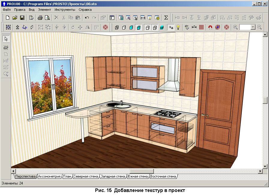
6. Double-click on the Tile folder, click on the tile texture you like, select it and drag it to the wall in the work area of the program window - the wall will be filled with the selected one. All walls are filled in the same way (Fig. 15).
 Having arranged all the pieces of furniture, you can change the material from which the furniture, doors, and MDF facade textures are made by following these steps:
1. Select a furniture object by clicking on it with the mouse button.
2. On the Materials tab of the additional Library window, open the Wood folder and select a texture for the furniture object by dragging it from the Library window onto the object. Perform this action for all wooden furniture objects, assigning the same or different textures.
- ADVICE
One way to select a material for elements is to drag the material while holding down the button Shift to the selected element, causing all elements in the project that previously had the same material as the element to also change their material.
3. Go to the Materials tab in the Facades folder and select the MDF texture by size for a specific kitchen facade.
4. Go to the Materials tab to the Tabletops folder and select a texture for the tabletops by selecting it and dragging it onto the surface with the mouse button (Fig. 16).
 Adding everything necessary items from the Libraries window, place lighting in the project using the following steps.
1. On the Elements tab of the additional Library window, select the Lighting folder by double-clicking on it (the folder contains various lighting objects).
2. Double-click on the required lighting fixture icon - the lamp highlighted with markers will be added to the work area of the project window.
3. Move the lamp to the planned location by dragging it with the mouse button and orienting it in space using the Object Properties window, Position tab. Similarly add required amount lighting fixtures and 3D models.
4. Click the Photorealistic display button on the View toolbar - after processing the data with the PRO100 program, you will get an image of a virtual room (Fig. 17).
5.Go to the Reports window, the Calculations tab displays the cost price of the product if there are program price list files for the site libraries used.