Page 3 of 6
Transportation of elements of prefabricated structures of reinforced concrete bridges
Individual structural elements of prefabricated reinforced concrete bridges from factories and landfills to the construction site are transported by rail, road transport or on trailers towed by tractors and tractors. Particularly large and oversized structures, such as blocks of spans, can be delivered by water on barges and other watercraft.
Transported structures are reliably secured to avoid accidental damage and prevent shifts under the influence of inertial, wind and dynamic loads. When transporting by rail, it is necessary to ensure compliance with the dimensions. If the length of the transported structure is greater than the length of the platform on which it is loaded, cover platforms are attached to both sides of the loading platform.
Storage of delivered structures at the installation site is carried out in the operating area of the installation mechanisms in a position convenient for further operations. Before installation, structures are cleaned of dirt and concrete deposits. If necessary, fittings outlets and embedded parts are also cleaned of rust and straightened.
Elements low mass(2-3 tons) in the simplest case are lifted by tying ropes around them. Elements of greater mass are lifted using special metal sling loops, securely embedded in the concrete of the structure in certain places. If the mass of the blocks exceeds 30-40 tons, special lifting devices are used that cover the structure with external parties. The mounted structures are suspended from the crane hook using slings made of steel ropes with a diameter of 16-38 mm or traverses - metal beams made of rolled steel. The use of slings requires an increase in the lifting height of the hook; the disadvantage of traverses is their large dead weight.
Installation of spans using jib cranes
The simplest method of installing split span structures is installation of span blocks using jib cranes, located below on the ground on the side of the mounted span or on the mounted part of the bridge.
When placing the crane on the ground (Fig. 9.9, a), the mounted beams are stored next to the crane so as to ensure installation by rotating the crane boom by 180°. It is possible to install beams “from wheels” without setting up a warehouse for beams on the construction site.
The beam intended for installation is slung, lifted, brought into the span by turning the crane boom and smoothly lowered onto the supporting parts, then freed from the slinging devices. The crane is moved to a new position and the installation of the next beam begins. The position of the crane and the location of the beams prepared for installation are selected in such a way as to ensure a minimum reach of the crane boom and eliminate the need to move it with a load.
Rice. 9.9 - Schemes for installation of beam reinforced concrete spans using jib cranes: 1 - crane; 2 - traverse; 3 - installed beam; 4 - installed blocks spans; 5 - beams prepared for installation
If the lifting capacity of one crane is insufficient for installation, two cranes are used to lift the beam from both ends simultaneously. The mounted beam is located in front of the cranes. Raising it first at the minimum boom reach, the beam is inserted into the span and installed on supports, increasing the reach of the crane booms. If the lifting capacity of the cranes does not allow installation of the beam at the required boom reach, the mounted block is first lowered at the maximum possible boom reach, then the cranes move forward, the beam is raised again, repeating the operations performed.
When installing bridges on a watercourse or if there is bad soils installation can be carried out by cranes placed on the mounted part of the bridge (Fig. 9.9, b). Installation of beams is done “from the head”. The crane carrying out the installation ahead must have sufficient lifting capacity over a long boom reach. Beams intended for installation are stored on the approach embankment, transported for installation using carts.
Installation of spans using gantry cranes
Installation of multi-span bridges and overpasses is convenient gantry cranes(Fig. 9.10), which can be used to perform the entire complex of construction and installation works. In construction practice, gantry cranes are used, either factory-made or assembled from inventory of bridge metal structures. To move the crane along the bridge, tracks are arranged on both sides along the subgrade or along working bridges (overpasses). The advantage of installation with gantry cranes is the ability to move the lifted elements both along the bridge by direct movement of the cranes, and across the bridge using load carriages.

Rice. 9.10 - Schemes for installing beams of spans using a gantry crane: 1 - beam submitted for installation; 2 - installed beam; 3 - mounted beams of the span; 4 - gantry crane; 5 - crane trestle
Installation of spans using console cranes
For installation of beam span structures railway bridges widely used jib slewing and fixed cranes with a lifting capacity of up to 130 t (Fig. 9.11).

Rice. 9.11 - Scheme of installation of beams of spans using a cantilever crane GEPC-130: 1 - counterweights; 2 - double-cantilever main beam of the crane; 3 - auxiliary pulley; 4 - main pulley; 5 - traverse; 6 - bridge support; 7 - installed beam; 8 - assembled bridge span; 9 - crane support platform
The main element of the crane is a double-cantilever beam (2), to the rear console of which counterweights (1) are attached, and the front cargo console is used for lifting and installing mounted beams on supports (6), for which the crane is equipped with a system of winches and pulleys. All structures and mechanisms of the crane are mounted on railway platforms, and movement is provided by a locomotive. Cranes GEK-50, GEK-80, GEK-120 and DGK-130, having a lifting capacity of 50, 80, 120 and 130 tons respectively, can install beams only along the axis of the track. Cranes PVK-70, GEPC-80 and GEPC-130 with a lifting capacity of 70, 80 and 130 tons allow the main beam to be rotated in a horizontal plane.
The span block intended for installation is transported on the railway platform directly to the bridge abutment and unloaded using jib cranes. After the platform is retracted, the console crane is supplied, the mounted beam is slinged and lifted using the cargo console. The crane with the suspended span structure is moved to the span being assembled, where the block is lowered and installed on supports. If the installation is carried out with a fixed console crane that installs blocks only along the axis of the track, transverse movement of the beams on the supports is required using hydraulic jacks. Rotary cranes ensure that the blocks are moved away from the track axis by up to 5.3 m, which allows the beams to be installed directly in the design position.
Installation of spans using special installation units
For the installation of road bridge spans, assembly units are used, which are a set of devices - mounting trusses or beams, cranes, trolleys that ensure the movement of beams along the bridge into the span being assembled, their transverse movement and installation in the design position. There is a large variety of mounting units.
Unit AMK-20-G7(Fig. 9.12, a), used for the installation of spans with beams up to 21 m long and weighing up to 24 tons, includes two self-propelled gantry cranes (2) with a lifting capacity of 12 tons each and an assembly bridge (4), on which crane tracks are located ( 1). Gantry cranes move both along the assembly bridge and along the approach embankments, for which the rear part of the assembly bridge is made in the form of a ramp with a slope of about 6%. Working in pairs, gantry cranes lift the assembled beam (3), transport it along the approach embankment, the assembled part of the bridge under construction, and further along the assembly bridge from the storage site to the assembled span and install it in the design position. After completing the installation of all beams in one span, the assembly bridge is moved longitudinally to the next span, continuity is restored crane tracks, thus preparing the unit for installation of the next span. When installing bridges with a width of more than 8 m, the unit must be dismantled and moved to a new position along the width of the bridge.

Rice. 9.12 - Scheme of installation of beam spans using the AMK-20-G7 installation unit (a) and the GP-2X30 cantilever-sluice crane (b)
Jib-sluice crane GP-2Х30(Fig. 9.12, b) allows the installation of beams with a length of 18-33 m and a weight of up to 60 tons. The crane includes a two-span continuous truss (6) with a counterweight (5), the middle and rear supports of which are mounted on trolleys that ensure movement of the crane along the rail 5.6 m gauge track on the assembled part of the bridge. The unit is self-propelled, for which the trolley (10) of the middle support is equipped with an electric drive.
Before installing the next span, the crane moves along the bridge until its front leg (9) reaches the opposite support of the span being installed, after which the front leg is supported on this support. The beam (3) intended for installation is supplied for installation on auxiliary trolleys. The beam will be mixed directly into the span cargo trolleys(8) cranes, which can also move on transverse beams (7) across the bridge. This allows you to install the beam in the required location along the width of the bridge.
Bridges wider than 7-8 m with beams up to 42 m long are mounted with a more powerful cantilever-sluice crane MShK-100 with a lifting capacity of 100 tons.
Installation in large blocks using floating equipment
In the practice of domestic bridge construction, a method of installing large bridges using large blocks made on the shore, with their delivery to the installation site by water, has been used (Fig. 9.13). The mass of blocks can reach several thousand tons. Thus, during the construction of a large bridge across the Volga, the mass of transported blocks was 2700 tons, and the length was 120 m. The mass of the superstructure structures of the bridge over the Moscow River in Luzhniki transported by water reached 5600 tons with a length of 198 m. Such large structures are transported by water on floating supports (floating systems) assembled from inventory universal pontoons of the KS type.

Rice. 9.13 - General form beam lattice span structure transported using floating supports
When installing spans using this method, scaffolding is arranged on the shore for assembling or concreting the assembled part of the structure, stands, etc. Blocks ready for installation are moved along special piers to the water, where floating supports are placed under them, previously submerged by filling part of the pontoons with water, mass which should be slightly greater than the mass of the transported structure. After placing the submerged floating system under the block, the water ballast is pumped out and the floating supports, trying to float, tear the structure away from the roll-out piers. Next, the floating systems, together with the span block, are transported by tugs to the span being assembled. Precise installation the block is made using winches and cables attached to anchors on the river bottom. After checking the position of the mounted block, the floating system is flooded by loading it with water ballast, and the structure is installed in the design position.
Roll-out piers, which ensure the movement of blocks from scaffolding to floating supports, are complex and expensive structures. Therefore, to reduce their length, a local deepening of the river bottom is often made between the piers, sufficient to install floating supports in a flooded state.
Monolining and waterproofing of spans
After installing the individual beams of the spans, they are combined by welding the reinforcement outlets or embedded parts in the diaphragms and concrete coating the joints.
The beams of railway spans have factory waterproofing, therefore, after the joint of the diaphragms is monolithic, the longitudinal gaps between the blocks and the deformation gaps between the spans are covered with long narrow metal sheets, lubricated with bitumen. Then the ballast is dumped and the superstructure is constructed.
When constructing road bridges, after the beams have been grouted, drainage pipes are installed in the holes of the slab and drainage triangle concrete is laid, on top of which waterproofing is applied.
Work on installing waterproofing, consisting of bitumen mastic reinforced with two layers of fiberglass mesh, is carried out at a temperature not lower than +5°C. Before use, bitumen mastic is heated in a bitumen boiler to a temperature of 150-170°C and applied while hot to the surface of the slab, spreading a layer of fiberglass mesh on top. Then a second layer of mastic is applied and a second reinforcing layer is laid, on which the last layer of mastic is applied.
Waterproofing is especially careful around drainage pipes. The insulating and reinforcing layers are placed inside the tubes and pressed against the walls of the tubes with a special glass. A protective concrete layer reinforced with metal mesh is laid on top of the waterproofing.
Suspended installation of the span- this is an installation method, as a result of which the assembled (enlarged) part of the span forms a console, which is a load-bearing element for subsequent installation by a crane.
For the suspended assembly of the span, the same method is used as for the semi-hinged assembly. Most often, a mast derrick crane of the UMK-2 type is used for installation, which is attached to the upper chord of the truss.
Suspended installation of the span - website

The suspended installation of spans can only be carried out if there is a work execution plan (WPP). Any deviation in the execution of work from the approved project must be previously checked by calculation and approved by the chief engineer of the bridge construction organization.
Mounted assembly is always advisable when the bridge is high above the water horizon, the river is deep, the bottom is rocky, there is intense shipping, and if it is necessary to allow ice drift or floods to pass during the installation period.
The advantages of the wall mounting method include:
- the possibility of installing long-span bridges from fully prefabricated blocks;
- versatility, characterized by the possibility of application under any local conditions, with supply to necessary cases blocks to the assembly site on boats or along the finished part of the bridge;
- the possibility of unifying the structures of spans and installation equipment;
- independence of work from atmospheric conditions;
- reducing the duration of bridge construction due to parallel work on the construction of supports and the manufacture of blocks, as well as due to the high rate of assembly of spans;
- significant reduction in the need for temporary support structures and erection metal compared to scaffolding or floating support methods;
- minimal labor intensity of work performed directly in the span.
The disadvantages of the wall mounting method are:
- the presence of assembly seams in the structure;
- the need to organize training grounds with heavy crane equipment and corresponding vehicles;
- the need for powerful crane installation equipment.
Types of suspended installation of superstructures

Suspended installation of a metal span - website
The suspended assembly of the span structure can be carried out either in one direction or from both sides to the middle, and in the latter case, to complete the installation, an operation is required to close the span structure, i.e., to connect both parts of it into one whole. With a balanced assembly, the spans are assembled evenly, that is, symmetrically from the support. Based on the above, the following types of assembly are distinguished:
Assembly from support to support of a metal truss

Mounted truss assembly from support to support - website

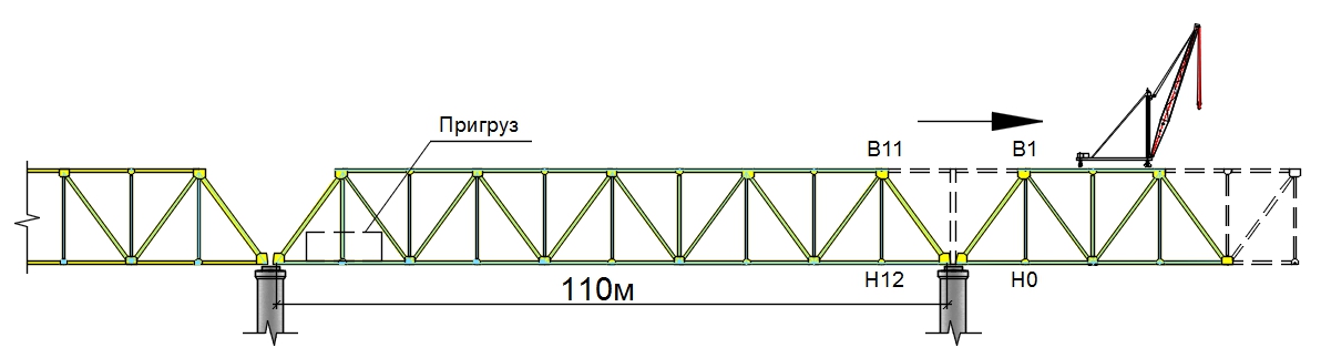 Rice. 1 (Diagram of suspended installation from support to support of a multi-span bridge covered with split beam trusses)
Scheme of suspended installation from supports to the middle of the span of a multi-span bridge covered with split beam trusses
The assembled span is temporarily attached to the previous one using auxiliary elements B11-B1 and H12-HO (Fig. 1 and Fig. 2). If the installation stresses exceed the permissible ones, then it is necessary to install temporary intermediate supports, the number of which is dictated by the maximum permissible length of the console.
If the third span is completely assembled in a canopy (Fig. 1), then the first panels of the second span should be additionally loaded to ensure proper stability of the span. The subsequent spans of continuous trusses are assembled in the same way.
If necessary hinged assembly of the first span, it is necessary to assemble a counterweight span structure on the shore and attach to it the span structure of the first span assembled under the canopy. Since when the abutments and embankment are ready, the assembly of the counterweight span structure is carried out on cages laid out on the embankment, then after the separation of the spans, the span assembled under the canopy has to be lowered to the height of the cabinet part of the abutment.
This installation method may be appropriate for a bridge with several spans, when the counterweight span structure can be used in one of the spans after disassembly.
Assembly from the support to the middle span of a metal truss 154 meters

Rice. 2 (Scheme of suspended installation from supports to the middle of the span of a multi-span bridge covered with split beam trusses)
When assembling from the supports to the middle of the span (Fig. 2), a rather complex operation is the establishment of joints in horizontal and vertical planes at the moment of closing the span. Therefore, this method is used mainly when installing arched bridges or for assembling single channel spans of long length, when spans of shorter length are adjacent to them on both sides, and the construction of temporary supports in the channel is impossible.
When installing a span in a suspended manner from support to support (Fig. 1), the forces at the root of the console will be significantly greater than when installing from supports to the middle of the span.
Assembling the arch from the support to the middle of the span
One of bright examples The use of the technology of suspended installation of a metal span structure from the supports to the middle of the span was used in 1932 during the construction of a single-span arch bridge at the Harbor Bridge in Sydney.

Additional measures for surface mounting
If structural elements cannot withstand the installation load during suspended installation, resort to one of the following measures:

Rice. 4 (Scheme of surface-mounted installation when the receiving console is put into operation).
- strengthen the span above the support with a truss (Fig. 5).


Rice. 5 (Scheme of suspended installation when the overhead truss is included in the work).

List of works before hanging installation
- in the warehouse of enlarged elements, all elements, bolts and plugs necessary for the uninterrupted operation of the shift of installers are prepared and placed in the order of delivery;
- check, test and put into good condition the installation crane, slinging devices, braces, torque wrenches, installation tools and personal protective equipment;
- prepare all materials required during the installation process for the installation of a temporary railway track, suspended scaffolding and pedestrian bridge, as well as painting and putty material;
- under the guidance of an experienced worker from the installation team, the enlarged elements are loaded onto a trolley and delivered for installation;
- hinged mounting cradles, ladders and safety cables are secured to the elements before being transported by crane to the installation site.
Instructions for suspended installation of metal spans
- Suspended installation should be carried out provided that a complete set of elements of the span structure is available and to complete the installation.
- To ensure continuous installation, structures are cleaned and enlarged in advance.
- Submission of enlarged elements and individual parts for installation is carried out in the order corresponding to the installation sequence developed by the design organization.
-
Installation of metal spans using the hinged method is carried out in accordance with the PPR approved specifically for this facility.
- The suspended installation is carried out using a rigid derrick crane UMK-2, which is moved along the upper chord of the span.
- With different heights of adjacent spans and a polygonal outline of the upper chord of the span, the installation crane can be placed on the roadway using a special stand that allows elements to be supplied under the crane.
- The enlarged elements are transported to the installation site by motor vehicle on TsNIIS trolleys. On each element, the center of gravity of the element and the places where it is slinged are marked in advance with oil paint. Each element on the trolley must lie on wooden supports in a stable position.
- During mounted assembly, work on making connections with high-strength bolts is carried out in two stages:
- Stage 1 - installation of plugs and high-strength bolts in the quantity provided for by the work organization project;
- Stage 2 - filling all holes and replacing plugs with high-strength bolts, tightening all bolts with a torque wrench to the design force and monitoring the bolt tension.
- The assembly crane is moved to the next parking place only after installing the calculated number of bolts and plugs in the assembly joints. The total number of plugs and high-strength bolts tightened to the design forces must be at least 20% of the number of holes in the connection. In this case, plugs must be at least 10% of the number of holes and at least 2 pcs., and bolts must be at least 10% of the number of holes and at least 1 pc. (see VSN 173-70, clause 9.5). Mounting plugs and bolts are installed in certain places of the main components.
- To prevent displacement of elements relative to each other and uneven transmission of forces, high-strength bolts are tightened in increments from the middle to the edges of the joint and in such a way that the bolts at the ends of the joint or element are tightened last.
- When installing high-strength bolts, the following requirements are met:
- Before installing them in the structure, bolts and nuts are cleaned of dirt, grease, and rust;
- the nuts must be turned along the entire thread of the bolt without using lubricant; the threads of the nut (but not the bolt) are lubricated before the final tightening of the bolt;
- the nuts are tightened to the value specified by the design using torque wrenches;
- the calibration of the keys should be monitored twice a shift (before the start of work and in the middle of the shift) with registration in the control calibration log of the keys;
- nuts tightened to a given torque are not secured with anything else;
- The degree of bolt tension is checked in the presence of a customer representative.
- If at least one bolt is found in a connection, the tightening force of which is 5% lower or 20% higher than the standard force, all bolts of this connection are subject to inspection.
- During the installation process, acceptance certificates for assemblies and connections for installation of high-strength bolts in accordance with Form 6.2 must be promptly drawn up, and the following logs must be kept:
- installation work;
- quality control of cleaning elements of steel bridge structures with connections using high-strength bolts;
- control calibration of keys for tensioning high-strength bolts according to shape;
- installation of high-strength bolts.
The procedure for installing elements of the span structure
- the lower chords of the trusses are installed;
- lower longitudinal and transverse connections are installed;
- the longitudinal beam of the bridge roadway is installed;
- ascending or descending braces are installed;
- longitudinal and transverse braces are installed in the upper chord of the previous panel (a delay in the assembly of longitudinal and transverse braces by more than two panels, including the one being mounted, is not allowed);
- the crane is moved to the next parking lot (one panel during installation);
- a transverse beam is installed;
- racks (or pendants) are mounted;
- the upper chords are mounted.
- Then the cycle repeats.
- The installation sequence diagram must comply with the PPR
Basic principles when installing a span
- Elements from the trolley are supplied for installation in a strictly vertical position of the cargo pulley of the assembly crane;
- The installation location of the trolley under the installation crane is fixed with firmly fixed stops on the rails of the temporary railway track, completely eliminating the possibility of the trolley falling;
-
The assembled sections must form closed triangles, ensuring the stability and immutability of the structure at all stages of installation;
- The elements are inserted into the assembly vertically by lowering the element from above under the influence of its own weight. When inserting an element into the fork, the gap of the fork must be checked and adjusted in advance;
- Alignment of holes in mounted structures is carried out using assembly pegs, eliminating the possibility of damage to the holes. Aligning mounting holes by tightening elements with a crane, as well as tightening mismatched holes with mandrels using a sledgehammer is prohibited;
- When installing plugs, use a hammer weighing no more than 2 kg;
- Belts, braces, pendants and racks are slung with two-loop slings 5 m long and 22 mm in diameter with earrings in the girth. Slinging a noose without earrings is not recommended. The connections are slung with universal (ring) slings made of soft rope with a length of L=2m and a diameter of Ø15 mm.
- For slinging longitudinal and transverse beams, clamps with bolted connections are used. To prevent the slings from fraying, wooden spacers are placed between them and the elements at the point of contact;
- Elements with a dirty or rusty joining surface must not be submitted for installation. If the period of cleaning the surfaces exceeds three days, they are subjected to repeated sandblasting. In case of bad weather, tarpaulin covers are kept ready to cover the cleaned surfaces.
- Depending on the span system and weight, its fastening and stability is carried out by installing counterweights or anchors.
- So, for example, when assembling cantilever and continuous span structures, the fastening can be a counterweight, which is a part of the span structure pre-assembled in some other way.
- When assembling split span structures of a multi-span bridge, each adjacent span structure can also be used as a counterweight, for which they are connected to each other with temporary ties.
- In the case of the installation of a single-span bridge, as well as the outer spans of multi-span bridges, the span structure can be secured with anchor rods made of steel cables (for small spans) or special rods when assembling bridges of large spans.
- During installation, the part of the span assembled under the canopy works as a console or beam, sealed at one end, then it must be in conditions under which such work is possible, and in some cases these conditions are provided by the truss system itself, and in other cases they have to be created artificially.
Occupational health and safety during suspended installation of superstructures
- all workers working at height undergo a special medical commission, training and special instructions;
- erectors of structures are provided with personal protective equipment - steeplejack belts, soft non-slip shoes, helmets;
- the aiming of elements is carried out only with the help of guy wires (it is strictly forbidden to do this directly with your hands);
- when all bolts are tightened to the design force, the lag is allowed by no more than three panels, including the one being mounted;
- when carrying out installation work in the river bed in the construction area, rescue craft (boats, boats) must be constantly on duty;
- suspended scaffolding is constructed according to designs approved by the chief engineer of the trust; Before operation, they will be inspected by a commission that issues an acceptance certificate.
- Dismantling of the scaffolding can be carried out in those panels where the installation and tightening of the bolts to the design force is completely completed.
Mounted installation in the construction of a railway bridge across the river. Dnepr in the city of Dnepr
Railway bridge design
The river bed is blocked by metal split spans with a triangular lattice, with a driveway below, 82.04 m long.
Span structures for one railway track are designed by analogy with standard projects. Each span, 11.25 m high and 5.7 m wide between the axes of the main trusses, is divided into 10 panels according to the scheme 8.25 x 4 + 8.02 x 2 + 8.25 x 4 m.
The elements of the chords and compressed braces of the main trusses are made of riveted box-section, the rest are welded of H-shaped section. The bridge deck consisted of metal cross members made of paired channels, the sidewalks were made of prefabricated reinforced concrete slabs resting on metal consoles attached to the walls of the longitudinal beams of the roadway. To lay communications, special boxes were laid on the same consoles.
Mounting connections are made with a diameter of 22 mm, made of 40X steel
The mass of the span is 291 tons. In total, for the construction of the bridge it was necessary to assemble metal structures of the bridge spans of more than 6,000 tons and install 383,000 high-strength bolts with a total weight of about 223 tons.
Surface mounting technology
The spans were mounted using a hinged method from pre-enlarged elements transported to the assembly site on watercraft. To ensure the unloading of elements of metal spans arriving by rail and preparing them for installation, a construction site with a set of necessary structures was organized on the left bank of the river.
At the construction site, railway tracks were laid, a gantry double-cantilever crane type KSK-30-42 with a lifting capacity of 30 tons was installed, serving a site 60 m wide, a stationary compressor room was built with a compressor with a total capacity of 80 m 3 /min, an air duct network was laid, and a UMK-2 crane was installed for loading enlarged elements onto watercraft.
Before the enlarged assembly, they carried out sandblasting connected surfaces. After cleaning the connecting surfaces of the main elements of the main trusses and gussets, they were enlarged using high-strength bolts.
The elements of the longitudinal beams of the roadway were combined in pairs by connections into spatial blocks with the elements of sidewalk consoles attached to them.
The suspended installation of the first span was carried out using an anchor span structure assembled on the shore on the approach embankment as a counterweight.
This decision was dictated economic feasibility, since the construction of assembly scaffolds in the first span is complicated by the fact that the river bottom is cluttered with metal and stone - the remains of a nearby bridge destroyed during the war.
The counterweight span structure was assembled and subsequently dismantled using the console of a KSK-30-42 type crane serving the construction site. The main assembly crane of the UMK-2 type and the auxiliary Zubach crane were also installed using a KSK-30-42 type crane.
The suspended installation of the first span with a UMK-2 crane began after installing the connecting elements and counterweight on the anchor span. The elements were fed under the installation crane on the floating craft. After supporting the erected span on the intermediate support, the rear installation crane of Zubach was also put into operation.
The connecting elements were dismantled using a Zubach crane after jacking up the mounted span on the intermediate support and removing the forces.
Then, an anchor device and connecting elements were installed on the supporting lower nodes of adjacent spans on the rear side of the mounted span, and then they began to install the next span using a UMK-2 crane. At the same time, on the previously installed span structure, Zubach’s auxiliary crane carried out work on assembling the span filling, installing roadway elements, etc.
During the suspended installation of metal spans, one of the most labor-intensive work is the construction of scaffolding to accommodate workers installing connections in the upper and lower nodes of the trusses. During the construction of a bridge across the river. Dnepr, a new type of assembly scaffolding was proposed and successfully used.

The installation scaffolding consisted of two parts:
- upper scaffolding suspended from an assembly crane, equipped with rotating cradles,
- lower rolling scaffolds on reconstructed lower inspection trolleys.
The upper scaffolding is suspended from the frame of an UMK-2 type assembly crane. The scaffolding consists of load-bearing cantilever beams and a set of suspended platforms:
- four fixed
- eight rotary (four on each side of the span).
The turntables rotate on hinges and occupy a working or transport position. In the working position, the platforms cover the horizontal connections approaching the node, in the transport position they are retracted to outer side trusses for unhindered movement of the crane with suspended scaffolds.
The use of a new type of scaffolding created favorable conditions for highly productive work of installers and completely eliminated the construction of temporary scaffolding and scaffolding.
High strength bolts and their tension
Mounting connections for surface mounting are made with a diameter of 22 mm. More than 25,000 bolts were installed on each span. High-strength bolts were tightened with torque adjustment using manual torque wrenches.
When tensioning the bolts, small impact wrenches of type IP3109 were used, creating a torque of 20 - 25 kgf∙m, large impact wrenches of type IP3106, creating a torque of 150 kgf∙m, and torque wrenches.
Tensioning bolts with torque wrenches to the design torque is labor-intensive work. In order to mechanize it on an experimental basis, the bolts were tensioned in one stage with the force being adjusted according to the angle of rotation of the nuts using serial calibrated pneumatic impact wrenches of the IP3106 type. The use of one-stage tensioning makes it possible to reduce the labor intensity of work by 2 times compared to the generally accepted technology of tensioning bolts with manual torque wrenches.
Page 4 of 6
Scope of installation work
IN composition of installation work includes transportation of structures from the manufacturing plant to the on-site warehouse, preparation of elements in the warehouse, delivery of them for installation and assembly of span structures with installation in the span.
Transportation of metal structures from factories is carried out by rail and mixed transport. Dimensions requirements impose restrictions on the dimensions of transported mounting blocks and determine maximum lengths entirely transportable structures that do not exceed 45 m.
Delivered to construction site The elements are stored, deformations that occurred during transportation are eliminated, they are cleaned of dirt and corrosion, markings are applied to facilitate installation, and enlarged assembly is carried out. Special attention is given to cleaning the contact surfaces of elements in joints at joints on high-strength bolts. Cleaning is carried out with steel brushes, by fire - with the flame of an acetylene-oxygen torch, followed by removal of combustion products with metal brushes and sandblasting machines. To protect against corrosion, the cleaned metal in the joint area can be coated with a preservative composition that does not reduce the frictional properties of the joints; in other places it can be painted.
To perform loading and unloading operations and other operations, warehouses are equipped with gantry and jib (railway, pneumatic-wheeled, crawler) cranes.
Mounting connections can be welded or with high-strength bolts. Welded installation connections performed automatically or semi-automatically. Manual welding allowed only as an exception. The diagram of a welded joint of a solid-wall beam with seams made by automatic welding was developed by the Institute of Electric Welding named after. E. O. Paton. Initially, the horizontal sheet of the lower belt (3) is welded (Fig. 9.14). Then insert (2) of the vertical wall is installed and vertical seams are made, after which insert (1) of the upper chord is welded. Horizontal seams are made using a welding machine, vertical seams are made by a special machine that moves vertically along the weld using a gear rack. Fillet welds along the upper and lower chords of beams are performed by semi-automatic welding in a carbon dioxide environment.
Rice. 9.14 - Assembly welded joint of the main beams with a solid wall (I-V - order of welds)
When connecting with high-strength bolts, during the assembly process, align the mounting holes, fixing the position of the elements with plugs and filling at least 10% of the holes with them. High-strength bolts are installed in the remaining holes in the joint, tightening them to the specified torque, after which the plugs are also replaced with bolts.
Tensioning high-strength bolts to the design force can be done in two ways.
First way based on controlling the torque. First, the bolts are tightened with pneumatic wrenches to a force of 80-90% of the calculated one. Reaching the design force is done using manual torque wrenches with a torque indicator. At the second way the value controlled during tension is the angle of rotation of the nut, which depends on the number of bodies (sheets) in the package being connected. The bolts are tightened using pneumatic wrenches, calibrated in such a way that during the tightening process the nuts are rotated to the required angle.
In addition to welded and bolted joints, combined bolted-welded joints are used. The walls are connected using high-strength bolts, and the belts are connected by automatic welding.
Assembly of spans on scaffolds
At assembly on scaffolding spans with through main trusses rest on scaffolding at each node, with a solid wall at all assembly joints. Therefore, for the assembly of through spans (Fig. 9.15), continuous scaffolding (1) is installed, supported by temporary supports (5), and for the assembly of spans with a solid wall, only temporary supports under the assembly joints are installed.

Rice. 9.15 - Installation diagram of a metal span with through main trusses on scaffolds: 1 - scaffolding; 2 - mounted part of the span; 3 - element to be installed; 4 - assembly crane; 5 - temporary supports
Scaffolding is made from universal bridge inventory structures (UIBMS), bridge inventory structures (MIS), and other inventory property. Wooden scaffolding is used in some cases during a feasibility study of the feasibility of their use.
UICM elements are assembled from isosceles angles with a shelf height of 75 to 120 mm. The cross-section of racks, belts, and other scaffolding elements can be composed of one, two, three or four corners. At the nodes, the elements are connected by gussets and plates on bolts with a diameter of 22 and 27 mm. MIC elements are made of steel pipes with a diameter of 95, 159 and 203 mm with flanges and eyes at the ends for connecting elements with bolts.
To assemble spans, gantry, jib and other assembly cranes are used, which can move along scaffolds or directly over assembled structures.
Assembly of spans can be tiered, sectional or combined.
At tiered assembly the span is mounted along its entire length from bottom to top. First, the lower chords are assembled on the scaffolding, the lower longitudinal connections, lay out the beam cage when driving below. This is the so-called bottom assembly. Then the top assembly is carried out - installation of lattice elements and upper chords with upper longitudinal braces. After assembling the entire span, the correct geometric dimensions are checked and high-strength bolts are installed. Tiered assembly provides high accuracy installation, but requires more installation time than other methods.
Sectional assembly involves panel-by-panel assembly of the span. When assembling the next panel (section), elements of the lower chord, lower longitudinal connections and roadway, grating, upper chords and upper longitudinal connections are laid out on the scaffolding, the nodes of the assembled panel are bolted together, after which the installation of the next panel begins. The advantage of sectional assembly- reduction of installation time.
If assembly is in progress combined method, then after the bottom-up assembly, the assembly of sections begins with the direct installation of bolts.
For ease of installation and adjustment of the structure when aligning the position, under each node, two assembly cages (3) (Fig. 9.16) are made of wooden beams, between which jacks (4) are installed under the center of the node, used when aligning the span.

Rice. 9.16 - Scheme of supporting the span components on the scaffolding: 1 - distribution package of rails; 2 - wedges; 3 - assembly cage; 4 - jack
After completion of all assembly operations, the spans are installed on the supporting parts. For this purpose, jacks are used, placed under the outermost so-called jacking transverse beams. In this case, under the nodes of the spans, safety cages with wedges are laid, with the help of which a gap of 2-3 mm is maintained between the cages and nodes during the entire lowering process.
Upon completion of installation work, the span is painted with two layers of paint, with preliminary cleaning of the elements from dirt, putty and primer.
Hinged and semi-hinged assembly of spans
At mounted and semi-mounted assembly The installation of spans is carried out from the support into the span and the span works like a cantilever. If the span at individual nodes rests on scaffolding or temporary supports (Fig. 9.17, a), a semi-mounted assembly takes place; if there are no temporary supports, it is mounted (Fig. 9.17, b).

Rice. 9.17 - Schemes for semi-mounted (a) and hinged (b) installation of metal spans: 1 - installation crane; 2 - anchor span assembled on the approach embankment; 3 - temporary connecting elements
Often hinged assembly is carried out in a balanced way on both sides of the support. This method is especially convenient for installing continuous spans. If beam split span structures are installed in this way, during the installation period they are combined into a continuous system by placing additional elements. Hanging installation can also be one-sided, when the hanging assembly is carried out in one direction from the support.
In semi-mounted assembly, several panels of the span are assembled on solid scaffolding. The length of the mounted section is selected from the condition of ensuring the stability of the structure when installing the following panels on top before resting on temporary supports. The number and placement of temporary supports are selected based on the stability of the spans at all stages of installation. The counterweight (anchor) part of the span (2) can be assembled on the approach embankment (see Fig. 9.17, b). In this case, there is no need to install special scaffolding. In this case, the structure of the subsequent span is used as an anchor, which is dismantled after the installation of the span in the first span is completed. The span, secured to the anchored structure by placing temporary elements (3), is mounted in a canopy or semi-canopy. The installation of spans covering the following spans is carried out in a similar manner. Elements for installation are fed along the mounted part of the structure or, in the case of a balanced mounted assembly, through water.
When mounted and semi-mounted installations, a certain order of assembly of spans is observed, in which, during the installation process, geometrically unchangeable sections in the form of triangles are sequentially assembled.
Installation of panels with downward braces (Fig. 9.18, a) begins with the installation of elements of the first chord and lower longitudinal braces. By placing braces II, rigid triangles are formed, which allows, after installing the longitudinal beams, to feed elements for installation directly into the assembled panel. Then the transverse beam, racks III, upper chords IV and upper longitudinal connections of the span are installed.

Rice. 9.18 - The procedure for installing metal bridge panels: a - with downward braces; b - with ascending braces
The installation of panels with ascending braces is more complicated (Fig. 9.18, b), since the closure of the triangles when installing from bottom to top occurs only after installing the elements of the upper chord, i.e. at the final stage of installation.
During mounted and semi-mounted assembly, assembly cranes, as a rule, move at the level of the upper chord of the mounted part of the span, for which a rail crane track is installed along the upper chords. Rigid-legged derrick cranes, whose lifting capacity does not depend on the boom reach, are most widely used as assembly cranes. The disadvantage of cranes is that they can only be mounted in front or to the side.
For the convenience of work on the installation of joints and connections, the units of the span are equipped with scaffolding.
Installation of spans by cranes
Construction time is significantly reduced when using all-transportable or large-block structures and installing them with cranes.
Fully transportable spans are installed directly on permanent supports. For the installation of prefabricated structures, temporary supports are constructed from inventory metal structures under the assembly joints. The installation work when installing spans with cranes includes slinging and lifting the mounting blocks, moving them into the span, installing them on temporary or permanent supports and constructing the bridge deck.
The installation of spans can be carried out using jib, gantry, cantilever cranes, as well as crane units. After installing the blocks, the position of the structure in plan and profile and the arrangement of joints are verified.
Rail-mounted jib cranes can be used to install spans with both a solid wall and through trusses. For spans up to 44 m, the installation of spans is carried out entirely, for large spans - in separate blocks, the weight of which is determined by the lifting capacity of the crane. The spans are assembled on the approach embankment. The crane with the mounted block is moved into the span along the mounted part of the bridge or along the scaffolding.
If the water depth is sufficient, as well as when installing blocks of large mass, floating cranes of industrial manufacture or assembled from bridge inventory structures are used.
The bridge deck of railway bridges running on crossbars is constructed by laying out bridge beams, attaching them to beams, and installing rails or counter rails. With a reinforced concrete slab, slab blocks are laid out or a monolithic slab is concreted. Then the waterproofing and bridge deck are installed. The slab installation work is carried out using jib cranes.
Sliding of spans
During the construction of metal bridges, longitudinal and transverse sliding of spans occurs.
Longitudinal slide used for installation of spans assembled on embankments along the axis of the bridge. When sliding small spans, slides made of channels, steel sheets or angles are attached to the bottom of the structure. The sliding structure is moved along the rails. To slide spans with a solid wall (Fig. 9.19), sliders are used on rollers combined into carriages (4) and installed on embankments, temporary and permanent supports. On the approach embankment, trolleys (2) can be used instead of carriages. An upper knurling path in the form of wooden crossbars and rails turned head down is attached to the lower chords of the beams. To prevent lateral displacements of spans during the sliding process, the rollers are equipped with flanges. Since the spans undergo deformations during the sliding process, the carriages are arranged in such a way that the position of the rollers corresponds to the outline of the upper rolling path. To do this, the rollers in the carriage are combined according to a balancing scheme. When using cylindrical (flabless) rollers, it is possible to slide without installing an upper knurling path directly along the lower chords of the beams (see node I in Fig. 9.19).

Rice. 9.19 - Diagram of sliding of metal spans with a solid wall: 1 - installation crane; 2 - trolley for moving the superstructure on the embankment; 3 - dead end for catching carts; 4 - carriages; 5 - avanback; 6 - temporary overlay
A sliding mechanism using gaskets made of antifriction materials is promising.
The sliding of spans with through main trusses (Fig. 9.20) is carried out on cylindrical rollers (4) with a device, in addition to the upper (2), also a lower (1) knurling path, and to ensure nodal transfer of the load from the own weight of the span during sliding the upper path is performed only under the lower nodes. If the beam cage is sufficiently strong, the rolling tracks can be arranged not under the chords of the main trusses, but under the longitudinal beams. In this case, the upper knurling path is made continuous.

Rice. 9.20 - Scheme of sliding of spans with through main trusses: a - first stage; b - second stage; c - knurling paths; 1 - lower knurling path; 2 - upper knurling path; 3 - floating support; 4 - rollers; 5 - lower chord of the truss
When longitudinally rolling spans, reducing the installation forces in the thrust structure and ensuring stability in the longitudinal direction is achieved by using a fore-beam, installing temporary intermediate supports, combining split spans into continuous ones and installing a counterweight on the rear of the span.
The sliding of spans can be done using a floating support. In this case, in the usual way, the span structure assembled on the embankment is longitudinally rolled into the first span until the size of the resulting cantilever is sufficient to provide a floating support and subsequently install the span structure on the permanent support. By bringing the floating support under the formed cantilever and pumping out water ballast from the floating system, the load from the weight of the span is transferred to the support. After this, the rear end of the span is hingedly supported on a carriage rolling along the lower knurling path, and the upper knurling path is dismantled. This ensures a constant value of support pressure on the carriage and the floating support, regardless of the stage of further sliding and the level of the end of the span resting on the floating support.
Sliding of spans is carried out using pulley hoists with manual or electric winches. To keep the span from moving under the influence of wind or the slope of the rolling track, as well as to facilitate precise aiming, in addition to traction pulleys, brake pulleys are also used. Winches are installed on an embankment or on a moving span. Fixed pulley blocks are attached to anchors (anchors) or to capital supports, movable blocks are attached to the superstructure being pushed up.
When sliding over a short distance or during conveyor-rear assembly with step-by-step sliding, hydraulic jacks can be used.
The assembly of spans can be carried out on scaffolds parallel to the axis of the bridge. In this case, to install spans in the design position, use transverse slider. To do this, under the supporting units of the span, piers are built from inventory metal structures, along which the lower rolling path is laid. The upper knurling paths are secured to the transverse beams. After moving to permanent supports, the span structure is jacked up and installed on the supporting parts.
Installation of spans using floating equipment
Installation of span structures using floating means allows for assembly to be organized away from the bridge alignment and, for multi-span bridges, can significantly reduce construction time.
The spans are assembled on solid scaffolds on the downstream side of the bridge under construction. To roll out spans into the channel and install them on floating supports, piers are arranged along which the assembled structure is moved transversely (more often) or longitudinally.
The features of transporting metal spans by water on floating supports and installing them in the design position are similar to the corresponding operations during the construction of reinforced concrete bridges (see previous lecture).
Page 5 of 12
For installation of metal spans uses heavy-duty cranes:
- floating with a carrying capacity of up to 1000 tons or more;
- self-propelled railways up to 250 tons;
- booms on automobile and caterpillar tracks with a lifting capacity of up to 170 tons;
- cantilever railways with a carrying capacity of up to 130 tons;
- self-propelled gantry with a lifting capacity of up to 65 tons;
Jib railway cranes type GEPC-130 can be installed in one block of metal solid-walled span structures of railway bridges with a ride on top up to 45.8 m long, and up to 55.8 m long - in two blocks (for this purpose, a temporary support is built in the span). The GEPC-130 has the ability to rotate the boom with a distance of up to 5.3 m from the track axis.
The crane is used to install enlarged spans, buildings or blocks on the approach to the bridge. They are laid out on sleeper cages along the approach embankment. The block is slung to the hook, the crane boom is rotated to the axis of the bridge, and the locomotive delivers the crane along the bridge, riding on top, to the place where the block is installed. After installing and securing the block to the supports, the crane returns back for the next block. Thus, installation is carried out “from the head”.
If it is necessary to pass along the assembled span of a bridge with a ride underneath, a crane with a block suspended on the boom can move inside the clearance of the through span.
The installation of a span with through main trusses with a span of 44.0 m is carried out using a GEPK-130 crane, also in one block, and the crane boom is inserted into the span, after which slinging is carried out using the lower chords or longitudinal beams span structure.
Sometimes a cantilever crane is used to install an enlarged (several panels long) spatial block of a superstructure with a span of 55, 66 and even 88 m. Then they are mounted using a hinged method (the number of intermediate supports in the first span is naturally reduced). The general diagram of the installation of such a span using a GEPC-130U crane is shown in (Fig. 6.16).
Rice. 6.16 - Schemes for installing spans with a ride on the bottom: a - solid span; b - large blocks; 1 - console crane; 2 - span; 3 - superstructure block; 4 - temporary span; 5 - bridge support; 6 - temporary support
Span structures with through main trusses of multi-span bridges can be mounted with a cantilever crane, but only with temporary supports along the axis of the bridge. First, temporary package span structures are installed (the crane appears to be stepping forward), then the blocks of the end-to-end span structure are installed. The crane, one by one dismantling the temporary packages, retreats, as it were, and carries out the installation, starting with the distant span.
Railway boomstaps EDK-500, EDK-1000, EDK-2000 with a lifting capacity of 80, 125 and 250 tons, respectively, etc. are widely used for the restoration and installation of single-span bridges, as well as overpasses (Fig. 6.17). To operate, it needs railway access and the ability to use outriggers (in this case, the crane’s maximum lifting capacity is realized).

Rice. 6.17 - Scheme of installation of blocks of spans with a jib crane EDK-1000: 1 - crane; 2 - new span; 3 - old span; 4 - block prepared for supply under the tap; 5 - block installed on supports
Installation “from the head” is limited by the lifting capacity of the cranes, which decreases significantly with increasing length of the span. If crane outriggers can be used, a check is required bearing capacity span structure on outrigger pressure during installation.
Domestic and foreign road jib cranes on automobile, pneumatic and crawler tracks, as well as on special chassis, have been widely used in recent years due to their significant lifting capacity. They are especially often used in the construction of road bridges, overpasses and overpasses for installation both “from the top” and “from below” (from under the bridge). A passage is arranged along the mounted span, and a crane (crawler, for example) is installed in the area of the support of the span being mounted. A block of the span structure is transported under the crane by a beam carrier, it is slung and mounted by turning the boom. It is imperative to check the span with non-monolithic beams for the load from a crane with a load.
Gantry cranes(Fig. 6.18) are characterized by a constant load capacity and the ability to move with a load. If the lifting capacity of one gantry crane is insufficient, the blocks can be mounted using two.

Rice. 6.18 - Scheme of installation of road steel-reinforced concrete 42-meter span structures using a K-451M gantry crane: 1 - metal structures warehouse; 2 - platform for installation of superstructure blocks; 3 - tap; 4 - block installed on supports; 5 - mounted span; 6 - crane trestle; 7 - driveway highway; 8 - stand
Installation with gantry cranes is advisable in urban environments, on dry floodplains and non-navigable rivers, when low-water overpasses and crane tracks can be installed. The height of capital supports should not exceed 15 m.
Cranes are placed on the approach embankment, which is not even filled to the design levels. Using a gantry crane, it is relatively easy to erect supports, install spans, and lay a prefabricated roadway slab.
The disadvantage is the need to construct crane tracks. Within the floodplain, expensive overpasses are required; in urban (dry land) conditions, the solution is much more economical.
The advantages of technology using gantry cranes are the absence of transfer of load from the weight of the erection crane to the erected span, the comparative simplicity and safety of installation work.
Floating cranes with a carrying capacity of 100, 200, 350 tons - self-propelled and fully rotating, it is especially advisable to rent them in large port cities. There are also floating cranes with a lifting capacity ranging from 500 to 3000 tons, which are usually used to lift sunken ships. In the 1980s, Mostostroy-6 used a floating crane with a lifting capacity of 1000 tons to build a bridge across the river. Neva near the village Maryino, Leningrad region. The cost of renting such cranes is quite high, but the technology is significantly simplified.
Assembly is carried out on shore in the operating area of the floating crane, after which the enlarged unit is transported on the crane hook to the installation site. Blocks can also be delivered to the crane on floating craft (barges, dinghies). The crane is secured in advance in the water area near the future bridge with Admiralty-type anchors and reinforced concrete suction anchors.
Slinging of large mass blocks is carried out according to a special project, taking into account the large diameter (up to 70 mm) of slings and the possibility of significant local loads on the span during slinging. It is advisable to use special traverses to avoid these loads. It is advisable to design a box-section span structure, which provides high torsional rigidity and low construction height. These qualities are required when installing large blocks.
If it is necessary to lift a block of mass Q using two inclined slings, determine the force in the sling using the formula
where α is the angle of inclination of the sling to the horizon.
Floating cranes are divided into floating cranes general purpose, specialized prefabricated and dismountable cranes installed on watercraft.
General purpose floating cranes are self-propelled full-rotating or fixed-rotating cranes with a lifting capacity from 5 to 1000 tons. In bridge construction they are used for the construction of supports and installation of spans.
As an example, (Fig. 6.19) shows a full-rotating floating crane with a lifting capacity of 5 tons, and (Fig. 6.20) shows a fixed-rotating Vityaz crane with a lifting capacity of 1000 tons. As a rule, floating cranes of this group are rented in ports.

Fig 6.19 - Floating crane PKL-5/30: 1 - rocker arm; 2 - thrust for changing the boom radius; 3 - engine room; 4 - rotary mechanism

Rice. 6.20 - Floating crane "Vityaz": 1 - pontoon; 2 - winch for changing the boom radius; 3 - winch; 4 - auxiliary lift winch; 5 - ship crane; 6 - main lift winch; 7 - boom; 8, 9 - suspensions of the main and auxiliary lifts, respectively
Specifications floating cranes are given in table 6.2.
Table 6.2 - Technical characteristics of some floating cranes

Specialized prefabricated floating cranes are produced specifically for the construction of bridges. Known floating cranes designed by the Transmost Institute are PRK-30/40, PRK-100, etc. Their characteristics are given in Table 6.3.
Table 6.3 - Technical characteristics of prefabricated floating cranes

The general view of such a crane is shown in (Fig. 6.21). The movement of floating cranes across the water area is carried out by anchor winches (Fig. 6.22) attached to pontoons. It must be taken into account that floating cranes narrow the river fairway.

Rice. 6.21 - Floating collapsible crane PRK-80: 1, 2 - suspensions of the main and auxiliary pulleys, respectively; 3 - jib guy; 4, 5 - winch cable of the auxiliary and main pulleys, respectively; 6 - swinging stand; 7 - jib pulley; 3 - valve block; 9 - pontoon; 10 - power plant; 11 - cargo winch; 12 - support unit; 13 - control cabin; 14 - boom; 15 - installation of a manipulator winch

Rice. 6.22 - Floating crane berthing diagram: 1 - floating crane; 2 - anchor winches; 3 - braces made of steel ropes; 4 - reinforced concrete suction anchors; 5 - support
In bridge construction, especially for the construction of supports, cranes mounted on dinghies of various types are widely used - based on barges of the river and sea fleet, pontoons of NZhM floating bridges, KS pontoons. Due to operation on water, the characteristics of the taps are somewhat deteriorated. Therefore, when choosing a crane, you should calculate the required lifting height of the hook, the crane’s lifting capacity, and the boom radius. It is necessary to check the buoyancy of the system, stability, draft taking into account roll and trim, the strength of the pontoon and superstructure, and determine the size of the dry side. In addition, it is necessary to determine dry and water ballast, select appropriate anchorage and tug boat. It is also necessary to determine the sufficient length of the cables from the anchor winches to the anchors to ensure the effective operation of the latter.
TYPICAL TECHNOLOGICAL CARD (TTK)
CONSTRUCTION OF BRIDGE SPRINGS
I. SCOPE OF APPLICATION
I. SCOPE OF APPLICATION
1.1. A standard technological map (hereinafter referred to as TTK) is a comprehensive organizational and technological document developed on the basis of methods of scientific organization of labor for performing the technological process and defining the composition of production operations using the most modern means mechanization and methods of performing work using a specific technology. TTK is intended for use in the development of Work Performance Projects (WPP), Construction Organization Projects (COP) and other organizational and technological documentation by construction departments. TTC is integral part Work production projects (hereinafter referred to as WPR) and are used as part of the WPR in accordance with MDS 12-81.2007.
1.2. This TTK provides instructions on the organization and technology of work on the construction of bridge spans.
The composition of production operations, requirements for quality control and acceptance of work, planned labor intensity of work, labor, production and material resources, measures for industrial safety and labor protection.
1.3. Regulatory framework for the development of a technological map are:
Standard drawings;
Construction codes and regulations (SNiP, SN, SP);
Factory instructions and technical conditions (TU);
Standards and prices for construction and installation work (GESN-2001 ENiR);
Production standards for material consumption (NPRM);
Local progressive norms and prices, norms of labor costs, norms of consumption of material and technical resources.
Reducing the cost of work;
Reducing construction duration;
Ensuring the safety of work performed;
Organization of rhythmic work;
Rational use of labor resources and machines;
Unification of technological solutions.
1.5. Workers are being developed on the basis of the TTK technological maps(RTK) to perform certain types of work (SNiP 3.01.01-85* "Organization of construction production") for the construction of bridge spans.
The design features of their implementation are decided in each specific case by the Working Design. The composition and degree of detail of materials developed in the RTK are established by the relevant contracting construction organization, based on the specifics and volume of work performed.
The RTK is reviewed and approved as part of the PPR by the head of the General Contracting Construction Organization.
1.6. The TTK can be tied to a specific facility and construction conditions. This process consists of clarifying the scope of work, means of mechanization, and the need for labor and material and technical resources.
The procedure for linking the TTC to local conditions:
Consideration of map materials and selection of the desired option;
Checking the compliance of the initial data (scope of work, time standards, brands and types of mechanisms used building materials, composition of the worker level) to the accepted option;
Adjustment of the scope of work in accordance with the chosen option for the production of work and a specific design solution;
Recalculation of calculations, technical and economic indicators, requirements for machines, mechanisms, tools and material and technical resources in relation to the chosen option;
Design of the graphic part with specific reference to mechanisms, equipment and devices in accordance with their actual dimensions.
1.7. A standard flow chart has been developed for engineering and technical workers (work foreman, foremen, foremen) and workers performing work in temperature zone III, in order to familiarize (train) them with the rules for carrying out work on the construction of bridge spans using the most modern means of mechanization, progressive designs and methods of performing work.
The technological map is designed for the following volumes:
II. GENERAL PROVISIONS
2.1. The technological map has been developed for a set of works for the construction of bridge spans.
2.2. Work on the construction of bridge spans is carried out by a mechanized team in one shift, the duration of working hours during a shift is:
2.3. The work sequentially performed during the construction of bridge spans includes the following technological operations:
Geodetic layout and fixation of the axes of support of the beams of the span on the supports;
Arrangement of assembly sleeper cages;
Enlarged assembly of beam blocks of the span structure;
Enlarged assembly of the middle block of the orthotropic plate;
Installation of the span.
2.4. When constructing bridge spans, the main materials used are: high-strength bolts M22x80 strength class 10.9 steel grade 40X, corresponding to GOST 52644-2006; high-strength nuts M22.10 strength class 10, steel grade 40X, corresponding to GOST 52645-2006; M24 washers steel grade St5sp2, corresponding to GOST 52643-2006; enamel PF-1331 according to GOST 926-82 *; primer GF-021 according to GOST 25129-82; electrodes 4.0 mm E-42 according to GOST 9466-75.
2.5. The technological map provides for the work to be carried out by a complex mechanized unit consisting of: mobile crane Liebherr LTM 1400-7.1 (max load capacity Q=400 tons at reach L=3.0 m, telescopic boom =60 m); mobile crane Liebherr LTM 1500-8.1 (max load capacity Q=500 tons at reach L=3.0 m, telescopic boom =84 m); truck tractor KamAZ-54115-15 with onboard semi-trailer SZAP-93271 (carrying capacity Q=25.0 t); automobile jib crane KS-45717 (load capacity Q=25 t); bulldozer B170M1.03VR (=4.28 m, h=1.31 m); dump truck KamAZ-6520 (load capacity Q=20.0 t).
Fig.1. Mobile crane Liebherr LTM 1500-8.1
Fig.2. Mobile crane Liebherr LTM 1400-7.1
Fig.3. Load characteristics of the KS-45717 truck-mounted jib crane
Rice. 4. Truck tractor KamAZ-54115-15 + semi-trailer SZAP-93271
Fig.5. Bulldozer B170M1.03VR
Fig.6. Dump truck KamAZ-6520
2.6. Work on the construction of bridge spans should be carried out in accordance with the requirements of the following regulatory documents:
III. ORGANIZATION AND TECHNOLOGY OF WORK EXECUTION
The condition of the construction site transferred by the Customer must comply with the terms of the contract and the requirements of section 4 Technical regulations on the safety of buildings and structures and other documents established by federal laws and laws of the constituent entities of the Russian Federation.
The construction site is considered prepared for installation work, if the site has been cleared and leveled, entrances and exits have been arranged, the site has been provided with electricity, and lighting has been installed.
3.4.3. Elements of the superstructure are delivered from the manufacturing plant to the on-site warehouse truck tractor KamAZ-54115-15 with semi-trailer SZAP-93271 .
3.4.4. Unloading and storing elements of the span structure at the on-site warehouse is carried out automobile jib crane KS-45717 in the area of operation of the installation crane with the help of workers who are part of the installation team.
It is prohibited to throw elements from vehicles or drag them on any surface. During loading, slings made of soft material should be used.
During loading and unloading operations, transportation and storage of elements of span structures, they must be protected from mechanical damage and exposure to precipitation.
Spacers must be placed between the horizontal rows of elements, one above the other strictly vertically. The width of the spacer is determined taking into account the crushing strength of the wood. The thickness of the gasket must ensure a gap from the top of the mounting loop of at least 20 mm and be at least 25 mm. The height of the stack should not exceed the width of the stack more than twice and should not exceed 2.5 m.
Storage areas are separated by through passages with a width of at least 1.0 m every two stacks in the longitudinal direction and every 25 m in the transverse direction. To pass to the ends of the elements, gaps equal to 0.7 m are arranged between the stacks.
The required supply of structures is determined depending on production needs, transportation distance and conditions of receipt of structures. In industrial construction, the time margin between delivery and installation of structures is up to two weeks. When determining the stock of structures, the need for a reserve in case of unforeseen delays in deliveries and the time required to complete the structures are also taken into account.
3.4.5. After the concrete underframes reach 70% of the design strength, the support axes of the metal beams of the spans are divided into supports. The initial data for alignment work are the coordinates and heights of the points of the geodetic alignment base accepted from the Customer.
To break down the support axes, an inventory tubular cast-off is used. The position of the alignment axes of the piles is fixed with steel wire strings, stretched along the axes on the cast-off, and transferred to the surface of the site using plumb lines lowered from the stretched strings.
Fig.7. Inventory cast-off
The alignment of the support axes should be carried out using a comparator tape in the longitudinal and transverse directions, guided by the working drawings of the span.
The procedure for carrying out marking work using the linear notching method. This method is used when determining points on the ground, slightly distant from the points and sides of the geodetic base. The method of linear serifs is that based on known distances " A ", "V "from fixed points (points of the geodetic basis)" A ", "IN "to a certain point of the structure" WITH "radii equal to segments" A ", "V " arcs are drawn on the ground, at the intersection of which the desired point is located. The length of the linear notches should not exceed the length of the measuring device, otherwise the notches will not be made accurately enough. When determining the points of critical structures using this method, including supports with a single-row arrangement of piles, the position the desired point " WITH "define not by two, but by three serifs, for example: from the reference point" A "and from two aim points" B " And " IN "radii equal to the calculated distances" A ", "b "And " V ", draw arcs at the intersection of which the desired point is located " WITH ".
The completed alignment work must be presented to the Customer's technical supervision representative for inspection and documentation by signing a Certificate of alignment of support axes on the ground in accordance with Appendix 2, RD 11-02-2006.
To the act of laying out the support axes, it is necessary to attach a schematic plan of the bridge crossing indicating the location of points, types and depth of placement of signs securing the GRO, coordinates of points, their chainage values and elevations in the accepted system of coordinates and heights.
3.4.6. Device sites for building a slipway start with planning and profiling the surface of the site according to given vertical marks bulldozer B170M1.03VR . The dimensions of the site must provide the possibility of placing installation cranes and have convenient entry.
The completed work on planning and profiling the surface of the site for the construction of a slipway must be presented to the Customer's technical supervision representative for inspection and documentation by signing an Inspection Certificate for hidden work in accordance with Appendix 3, RD 11-02-2006.
3.4.7. For device installation site KamAZ-6520 dump trucks crushed stone of the 40-70 mm M800 fraction is delivered to the planned site and leveled bulldozer B170M1.03VR layer 25-30 cm and compacted vibrating plate TSS-VP90N in 8 passes along the trail.
The completed work on the construction of the crushed stone base of the site must be presented to the Customer's technical supervision representative for inspection and documentation by signing an Inspection Certificate for hidden work in accordance with Appendix 3, RD 11-02-2006.
On a planned and compacted crushed stone base truck crane KS-45717 PDN-14AtV road slabs are being laid.
Fig.8. PDN-14AtV slab, L=6000 mm, B=2000 mm, H=140 mm, P=4.2 t, V=1.68 m
Fig.9. Reinforced concrete laying scheme slabs on a construction site
The completed work on the installation of the installation site must be presented to the Customer's technical supervision representative for inspection and documentation by signing an Inspection Certificate for critical structures in accordance with Appendix 4, RD 11-02-2006.
This act must be accompanied by an executive geodetic diagram indicating its dimensions in plan, profile and absolute surface elevations.
Upon completion of the installation of the span, the crushed stone base and slab covering are dismantled and removed from the construction site.
3.4.8. Slipway for assembling the superstructure arranged from foundation blocks FBS 1200x600x600 mm (26 pcs.) and FBS 1200x600x300 mm (4 pcs.), mounted on reinforced concrete slabs 2P30.18 size 3000x1750x170 mm (24 pcs.). Placed on top of FBS wooden beam section 150x150 mm (6.0 m).
The completed work on the construction of the slipway must be presented to the Customer's technical supervision representative for inspection and documentation by signing the Inspection Certificate for critical structures in accordance with Appendix 4, RD 11-02-2006.
This act must be accompanied by an executive geodetic diagram indicating the dimensions of the slipway in plan, profile and absolute elevations of the top of the surface.
Fig. 10. Plan of the slipway for assembling the superstructure
3.4.8.* Temporary support BO2 assembled from a rolled metal profile. The total weight of the metal of the temporary support is 8149.3 kg (see Fig. 11).
________________
*Numbering corresponds to the original. - Database manufacturer's note.
Installation of temporary support metal structures is carried out in accordance with the requirements of SNiP, Working Design, approved Work Project and manufacturer's instructions. Replacement of metal structures and fastening materials provided for in the project is allowed only in agreement with design organization and the customer.
Specification of metal structures
Table 1
|
Name |
Unit weight, kg |
||
Fig. 11. Temporary support BO 2
Welded installation connections should be made in accordance with GOST 5264-80 * using E42A electrodes in accordance with GOST 9467-75 *. The height of welds not indicated on the drawings should be taken according to the smallest thickness of the elements being welded. The minimum thickness of fillet welds should be taken according to table 38 SP 16.13330.2011.
All welds must be presented to the Customer's technical supervision representative for inspection and signing of the Inspection Certificate for hidden work in accordance with Appendix 3, RD 11-02-2006.
The progress and results of welding work must be entered in the Welding Work Log (form F-56,).
Paint metal structures with two layers of PF-1331 enamel over a layer of GF-021 primer with a total thickness of at least 80 microns after all welding work has been completed. The appearance of the paint and varnish coating must correspond to the indicators of class V according to GOST 9.032-74 *.
The anti-corrosion coating of metal structures and embedded parts after installation by welding must be restored by painting with two layers of PF-1331 enamel over a layer of GF-021 primer with a total thickness of at least 80 microns.
Apply a layer of primer to the weld seams with a brush or roller until the surface is completely primed.
The progress and results of work on applying anti-corrosion coating and painting must be entered in the Journal of works on waterproofing, anti-corrosion protection, painting of steel structures (form F-62, Rosavtodor order N IS-478-r dated 05.23.2002).
The completed work on the installation of a temporary support must be presented to the Customer's technical supervision representative for inspection and documentation by signing an Inspection Certificate for critical structures in accordance with Appendix 4, RD 11-02-2006.
This act must be accompanied by an as-built diagram of the support indicating its dimensions in plan and profile.
3.4.9. Temporary support is being installed scaffolding P1(see Fig. 12). The total weight of the metal of the P1 scaffolding is 780.2 kg, taking into account the weight of the welds 2% = 795.8 kg. The total volume of timber for scaffolding is 0.95 m.
Fig. 12. Scaffolding P1
The completed work on the installation of scaffolding must be presented to the Customer's technical supervision representative for inspection and documentation by signing an Inspection Certificate for critical structures in accordance with Appendix 4, RD 11-02-2006.
An as-built diagram of the scaffolding indicating its dimensions in plan and profile must be attached to this act.
3.4.10. The completion of preparatory work is recorded in the General Work Log (The recommended form is given in RD 11-05-2007) and must be accepted according to the Act on the implementation of occupational safety measures, drawn up in accordance with Appendix I, SNiP 12-03-2001.
3.5. Installation of the span
3.5.1. The construction of bridge spans is carried out in the following sequence:
Assembly of span beam blocks;
Arrangement of supporting parts;
Installation of beams in spans;
Securing beams against tipping;
Installation of the middle block of the orthotropic slab;
Combining beams and block into a span structure.
3.5.2. On the prepared slipway, the enlarged assembly of the blocks of span structures and the middle block of the orthotropic slab is carried out. The assembly joints of the main beams are assembled using high-strength M22 bolts.
The enlarged assembly of spans that are composite along the length should be carried out in the technological sequence determined by the installation project, according to the enlarged assembly maps, and also in strict accordance with the operating instructions for the installation units. Welding or tacking of mounting fixtures to the main structures is not allowed.
Workers who have undergone special training, confirmed by an appropriate certificate, can be allowed to make connections using high-strength bolts with controlled tension.
Before assembly, the contact surfaces of bolted joints must be inspected and cleaned of dirt, ice, loose rust, loose scale, oil, and paint (except for factory primer).
Hardware (bolts, nuts, washers) must be cleaned of factory preservative grease before being installed in connections.
Each high-strength bolt is class B and class A precision connections load-bearing type complete with one nut and two round washers - for the bolt head and one or two washers for the nut.
In connections where bolts are subject to shear and crushing, the bolt thread should be outside the hole, and the smooth part of the rod should not protrude from the washers.
Each tightened bolt must have at least one full thread remaining on the nut side.
The nuts of high-strength bolts, tensioned to the design forces, should not be secured with anything additional. In other bolted connections, the nuts are secured against loosening using spring washers in accordance with GOST 6402 or locknuts.
Connection bolts must be tightened first pneumatic impact wrench IP3112 with the highest tightening torque equal to 100 N*m to 50-90% of the design force, then tighten with a torque wrench to the design force with tension control based on the magnitude of the applied torque. The tightening forces of the bolts are controlled by the pressure in the pneumatic system.
Hydraulic torque wrenches of the KLTS type should be calibrated before their first use (or after repair), again after tensioning the first and second thousand bolts, and then periodically after tensioning every five thousand bolts. All torque wrenches in use must be numbered.
Manual torque wrenches should be calibrated at the beginning and in the middle of each work shift with a test weight. The results of their calibration should be entered into a special Logbook for the control calibration of wrenches for tensioning high-strength bolts in the form F-60, order of Rosavtodor dated May 23, 2002 N IS-478-r.
The tension of the bolts must be carried out from the areas with a tight fit of the parts of the package being connected to the areas with gaps. The bolts located near the plugs should be retightened after the plugs are removed. In connections with tightened bolts, no gaps are allowed between the plane of the structure, washers, nuts and bolt heads.
The quality of tightening of the bolts should be constantly checked by tapping them with a hammer weighing 0.4 kg, while the bolts should not shake or move. The results of the assembly of beams must be entered in the Logbook for installing high-strength bolts (form F-59, order of Rosavtodor dated May 23, 2002 N IS-478-r).
Fig. 13. General view of the enlarged block of the span =37.58 m
3.5.3. Movable supporting parts must be installed according to the design, taking into account the air temperature at the time of installation, as well as shrinkage and creep of the concrete of the spans. When installing supporting parts, marks should be applied to mark the relative initial position of their elements, and a mark indicating the temperature when installing spans.
3.5.4. Rubber and rubber-fluoroplastic supporting parts should be installed directly on under-truss platforms, prepared and verified within the deviations indicated in Table 1, and steel and glass ones - on a perimeter-formed layer of unset cement-sand mortar or polymer concrete indicated in Table 2.
It is permissible to install steel and glass support parts on wedges and adjusting devices, followed by injecting the gaps with epoxy resin-based glue and removing the wedges.
Before injecting the gaps, they should be sealed and fittings for injecting glue should be installed. At least four fittings must be installed around the perimeter of each supporting part. The fittings should be installed directly into the gap (when sealing it with a harness) or into holes specially provided by the design in the supporting parts.
Before installation, the rubbing surfaces of steel supporting parts and rolling surfaces must be thoroughly cleaned and rubbed with graphite or coated with molybdenum disulfide lubricant.
The installation of supporting parts is documented by an act of inspection and acceptance of the installed supporting parts.
3.5.5. Before installing spans and individual beams on supports using jib cranes, you must:
Preliminarily check the embankment of approaches, the condition of paths and platforms;
Strength and stability of previously installed structures;
funds will NOT be debited from your account and we will not receive payment confirmation.
In this case, you can repeat the purchase of the document using the button on the right.
An error has occurred
The payment was not completed due to a technical error, cash from your account
were not written off. Try waiting a few minutes and repeating the payment again.