Water-based types of heated floors continue to improve, remaining popular among consumers. One of the recognized leaders is the Italian company Valtec.
Pros of the Valtec system
Before starting installation and selecting a mixing unit for a Valtec heated floor, it is necessary to analyze the advantages of this type of water circuit.
- Thanks to quality materials, durable fasteners ensure reliable operation.
- Developed in the form of modules, the components fit together precisely, eliminating the risk of leaks.
- The manufacturer has provided for the production of related materials necessary for thermal and waterproofing equipment.
Calculation instructions
In order to correctly develop a project for laying a heated floor, you will need a preliminary calculation of the main indicators, focusing on their average values.
Do-it-yourself installation of water heated floors
It is necessary to take into account various factors, including the role of the water floor as the main type of heating or its use as additional source heat. Since a detailed calculation for doing it yourself is complex process, in practice, averaged parameters are used.

Once the key parameters have been determined, a diagram can be developed in which the most efficient pipe laying is determined on an exact scale. After this, their total length is calculated. At the same time, it is thought through where the pumping and mixing unit and control elements will be located.
Key characteristics of the mixing unit
In order for the installed water circuit to function effectively, it is necessary to correctly calculate the entire system and correctly install the mixing unit for the Valtec heated floor in accordance with the provisions reflected in the instructions included with the kit.

Parameters of the pumping and mixing unit:

The pipes have an external thread with a Eurocone connection.
Pumping and mixing unit for heated floors
Functionality
The main purpose of the pumping and mixing unit is to stabilize the temperature of the coolant when entering the water circuit by using water from the return line for mixing. This ensures optimal functioning of the heated floor without overheating.
The Combi unit design includes the following service elements:

The following organs are used to adjust the unit:
- a balancing valve on the secondary circuit, which ensures mixing in the required proportion of coolants from the supply and return pipelines to ensure the standard temperature;
- balancing shut-off valve on the primary circuit, responsible for supply to the unit required quantity hot water. It allows you to completely shut off the flow if necessary;
- a bypass valve that allows you to open an additional bypass to ensure the pump operates in a situation where all control valves are closed.
The connection diagram has been developed taking into account the possibility of connecting to the pumping and mixing unit the required number of floor heating branches with a total water consumption not exceeding 1.7 m 3 /h. The calculation shows that a similar amount of coolant flow with a temperature difference of 5°C corresponds to a power of 10 kW.
In the case of connecting several branches to the mixing unit, it is advisable to select collector blocks from the Valtec line with the designation VTc.594, as well as VTc.596.
Installation algorithm
After the preliminary calculation of all components has been completed, the actual installation of the heated floor begins, which involves going through several stages.

Settings
To connect pipes to distribution manifolds, a pipe cutter is used to cut the required length, a calibrator, a chamfer and a compression fitting. It is difficult to carry out detailed calculations at home, so be sure to study the instructions, which detail the settings of the pumping and mixing unit in a certain sequence.

k νb = k νt ([(t 1 – t 12) / (t 11 – t 12)] – 1),
where k νt – coefficient = 0.9 valve capacity;
t 1 – supply water temperature of the primary circuit, °C;
t 11 – temperature of the secondary circuit at the coolant supply, °C;
t 12 – return pipeline water temperature, °C.
The calculated value k νb must be set on the valve.

Consumption G 2 (kg/s) is determined by the formula:
G 2 = Q / ,
where Q – total thermal power water circuit connected to the mixing unit, J/s;
4187 [J/(kg °C)] – heat capacity of water.
A special program is used to calculate pressure losses hydraulic calculation. To determine the pump speed, which is set using a switch, according to the calculated indicators, a nomogram is used, which is in the instructions attached to the heated floor design.

- Setup operations in progress balancing valve on the primary circuit.
- The thermostat sets the temperature required for comfortable heating.
- A trial run of the system is being carried out.
If there are no leaks, all that remains is to perform concrete screed, and after it has completely hardened, lay the flooring.
Video: Warm floor with pumping and mixing unit VALTEC
The VALTEC COMBIMIX (VT.COMBI) pump and mixing unit is designed to maintain a given temperature of the coolant in the secondary circuit (due to mixing from the return line). Using this unit, it is also possible to hydraulically link an existing high-temperature heating system and a low-temperature underfloor heating circuit. In addition to the main control elements, the unit also includes the entire necessary set of service elements: an air vent and drain valve, which simplify maintenance of the system as a whole. Thermometers make it easy to monitor the operation of the unit without the use of additional devices and tools.

It is permissible to connect to the VALTEC COMBIMIX node unlimited amount heated floor branches with a total power of no more than 20 kW. When connecting several branches of a heated floor to a node, it is recommended to use VALTEC VTc.594 or VTc.596 collector blocks.
The main adjustment elements of the pumping and mixing unit:
1. Secondary circuit balancing valve (position 2 on the diagram).
This valve ensures mixing of the coolant from the return collector of the heated floor with the coolant from the supply pipeline in the proportion necessary to maintain the specified temperature of the coolant at the outlet of the COMBIMIX unit.

The valve setting is changed using a hex wrench; to prevent accidental rotation during operation, the valve is secured with a clamping screw. The valve has a scale with capacity values Kv τ valve from 0 to 5 m 3 / h.
Note: Although the valve capacity is measured in m3/h, it is not the actual coolant flow rate passing through this valve.
2. Balancing shut-off valve of the primary circuit (pos. 8 )
Using this valve, the required amount of coolant is adjusted that will flow from the primary circuit to the unit (unit balancing). In addition, the valve can be used as a shut-off valve to completely shut off the flow. The valve has an adjusting screw with which you can set the valve capacity. The valve is opened and closed using a hex key. The valve has a protective hex cap.

3. Bypass valve (pos. 7 )
During operation of the heating system, a mode may arise when all control valves of the heated floor are closed. In this case, the pump will operate in a muted system (without coolant flow) and will quickly fail. In order to avoid such modes, there is a bypass valve on the unit, which, when the valves of the underfloor heating system are completely closed, opens an additional bypass and allows the pump to circulate water through a small circuit in idle mode without loss of functionality.

The valve is activated by the pressure difference created by the pump. The pressure difference at which the valve opens is set by turning the regulator. On the side of the valve there is a scale with a value range of 0.2-0.6 bar. Pumps recommended for use with COMBIMIX have a maximum pressure of 0.22 to 0.6 bar.
After the heating system is completely assembled, pressure tested and filled with water, it should be adjusted. The adjustment of the control unit is carried out together with the commissioning of the entire heating system. It is best to adjust the unit before starting to balance the system.
Algorithm for setting up the control unit:
1. Remove the thermal head ( 1 ) or servo drive.
To ensure that the control valve actuator does not affect the assembly during adjustment, it must be removed.

2. Set the bypass valve to the maximum position (0.6 bar).
If the bypass valve is triggered while the unit is being configured, the setup will be incorrect. Therefore, it should be set to a position in which it will not work.

3. Adjust the position of the secondary circuit balancing valve (pos. 2 on the diagram).
The required capacity of the balancing valve can be calculated independently using a simple formula:
![]() t 1
-
coolant temperature in the supply pipeline of the primary circuit;
t 1
-
coolant temperature in the supply pipeline of the primary circuit;
t 11 - temperature of the coolant in the supply pipeline of the secondary circuit;
t 12 - coolant temperature in the return pipeline (both circuits are the same);
Kv τ - control valve capacity coefficient, for COMBIMIX is assumed to be 0.9.
Received value Kv set on the valve.

Calculation example
Initial data: calculated temperature of the supply coolant- 90 °C; design parameters of the heated floor circuit 45- 35 °C.
Received valueKv
set on the valve.
4. Set the pump to the required speed.
G2 = 3600 Q / c · ( t 11 - t 12), kg/h;
Δ P n = Δ P s + 1, m water. Art.,
Where Q- the sum of the thermal power of all loops connected to COMBIMIX; With- heat capacity of the coolant (for water - 4.2 kJ/kg °C; if a different coolant is used, the value should be taken from the technical passport of this liquid); t 11 , t 12 - temperature of the coolant on the supply and return pipelines of the circuit after the COMBIMIX unit. Δ P c - pressure loss in the design circuit of the heated floor (including collectors). This value can be obtained by performing a hydraulic calculation of the heated floor. To do this, you can use the calculation program VALTEC.PRG.
Using the pump nomograms presented below, we determine the pump speed. To determine the pump speed, a point with the corresponding pressure and flow rate is marked on the characteristic. Next, the nearest curve above this point is determined, and it will correspond to the required speed.


Example
Initial conditions: underfloor heating with a total power of 10 kW, pressure loss in the most loaded loop of 15 kPa (1.53 m of water column).
Water flow in the secondary circuit:
G 2 = 3600 ·Q / c · (t 11 - t 12 ) = 3600 10 / 4.2 (45- 35) = 857 kg/h (0.86m 3 / h).
Pressure losses in circuits after the unitCOMBIMIXwith a reserve of 1 m of water. Art.:
Δ Pn= Δ PWith+ 1 = 1.53 + 1 = 2.53 m aq. Art.
Pump speed selected -MEDby point(0.86 m 3 / h; 4.05 m water column):

If it is not possible to calculate the pump, then you can skip this step and proceed directly to the next one. At the same time, set the pump to the minimum position. If during the balancing process it turns out that there is not enough pump pressure, you need to switch the pump to a higher speed.
5. Balancing the branches of a heated floor.
Close the balancing shut-off valve of the primary circuit. To do this, open the valve cover and use a hex wrench to turn the valve counterclockwise until it stops.

The task of balancing heated floor branches comes down to creating the required coolant flow in each branch and, as a result, uniform heating.
The branches are balanced with each other using balancing valves or flow regulators (not included in the COMBIMIX kit; flow regulators are included in the VTc.596.EMNX manifold block). If there is only one circuit after COMBIMIX, then nothing needs to be linked.
The balancing process is as follows: balancing valves/flow regulators on all branches of the heated floor are opened to the maximum, then a branch is selected in which the deviation of the actual flow from the design one is maximum. The valve on this branch closes to the required flow rate. Thus, it is necessary to adjust all the branches of the heated floor.
Example
First, let's determine the required coolant flow in the primary circuit. To do this, you can use the following formula:
G 2 = 3600 ·Q / c · (t 1 - t 2 ),
where Q is the sum of the thermal power of all devices connected after COMBIMIX; c is the heat capacity of the coolant (for water - 4.2 kJ/kg °C; if a different coolant is used, the value should be taken from the technical passport of this liquid); t 1, t 2 - coolant temperature on the supply and return pipelines of the primary circuit (the coolant temperatures in the return pipeline of the primary and secondary pipelines are the same).
For a heated floor with a total power of 10 kW with a design temperature of the supply coolant of 90 ° C, the design parameters of the heated floor circuit are 45-35 ° C, the coolant flow in the primary circuit will be as follows:
G 2 = 3600 ·Q / c · (t 1 - t 2 ) = 3600 · 10 / 4.2 · (90 - 35) = 155.8 kg/h.
When calculating, the designer determined that the pressure loss on the balancing valve of the unit should be 9 kPa (0.09 bar), in order for the coolant flow in the primary circuit to be 0.159 m 3 / h, k v of the valve should be:
k v = 0.159 /√0.09 = 0.53 m 3 /h.
To determine the number of revolutions, you can not count kv but use the nomogram given below. To do this, plot the required flow through the primary circuit and the required pressure loss across the valve on the graph. The nearest inclined line will correspond to the required setting (number of revolutions). To improve accuracy, you can interpolate the obtained values.

The first line of the table indicates the position, the second line of the table indicates the number of turns of the adjusting screw. (In this example, 2 and ¼.) The third line shows Kv for this setting, as you can see it practically coincides with the calculated one.
Setting the valve speed:
The correct adjustment of the valve should start from the position of the valve being fully closed; using a thin flat-head screwdriver, tighten the adjusting screw until it stops and put a mark on the valve and on the screwdriver.
 Using the valve setting table, turn the screw the required number of revolutions. To fix the speed, use the marks on the valve and screwdriver. (following the example, you need to make 2 and ¼ turns).
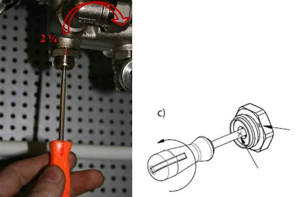 Using a hex key, open the valve until it stops. The valve will open exactly as much as you turn the screwdriver. After setting the valve, you can open and close it using a hex wrench, while maintaining the capacity setting.
 In the same way, all other balancing valves of the heating system are calculated. The number of valve revolutions (or the setting position is determined according to the methods of balancing valve manufacturers).
Second balancing method system is that the settings of all valves are set “in place”. In this case, the setting values are determined based on the actually measured coolant flow rates for individual branches or systems.
This method They are usually used when setting up large or critical heating systems. During balancing, special devices are used - flow meters, with which you can measure flow in individual directions without opening the pipeline. Balancing valves with fittings and special pressure gauges are also often used to measure the pressure drop, which can also be used to determine the flow rate in individual areas. The disadvantage of this method is that instruments designed to measure flow are too expensive for one-time or infrequent use. For small systems, the cost of the devices may exceed the cost of the heating system itself.
When balancing using this method, COMBIMIX is configured as follows:
Fix the flow meter on the pipeline through which COMBIMIX is connected to the heating system. Calibrate and configure the flow meter according to the instructions for the flow meter.
Then smoothly open the balancing valve using a hex wrench, while recording the change in coolant flow. As soon as the coolant flow corresponds to the design, fix the position of the valve using the adjusting screw.
Example
As for the previous example, the coolant flow rate is first calculated.
For a heated floor with a total power of 10 kW, a design temperature of the supply coolant of 90 °C, and design parameters of the heated floor circuit of 45-35 °C, the coolant flow in the primary circuit will be as follows:
G 2 = 3600 · Q / c · (t 1 - t 2) = 3600 · 10 / 4.2 · (90 - 35) = 155.8 kg/h (0.159 m 3 / h).
Close the balancing valve completely using the hexagon:
 Smoothly open the valve using a hexagon and record the flow rate on the flow meter until the flow rate reaches the design value (in the example, 0.159 m 3 /h).
 After the coolant flow has been established, fix the position of the shut-off valve using the adjusting screw (tighten the adjusting screw clockwise until it stops).
 After the adjusting screw is fixed, the valve can be opened and closed using a hexagon, the setting will not be lost.
For small systems
In the absence of a project and complex measuring instruments, the following balancing method is acceptable:
IN ready-made system turn on the boiler and central pump (or other heat supply source), then close all balancing valves on all heating devices or branches. After this, the heating device that is installed furthest from the boiler (heat supply source) is determined. The balancing valve in this device opens completely; after the device has completely warmed up, it is necessary to measure the temperature difference of the coolant before and after the device. Conventionally, we can assume that the temperature of the coolant is equal to the temperature of the pipeline. Then we move on to the next heating device and smoothly open the balancing valve until the temperature difference between the forward and return pipelines coincides with the first device. Repeat this operation with all heating devices. When the turn comes to the COMBIMIX unit, its adjustment should be carried out as follows: If the coolant temperature in the supply pipeline is equal to the design one, then the balancing valve of the primary circuit should be smoothly opened until the readings on the thermometers of the supply and return pipelines of the secondary circuit are equal to the design ± 5 °C.
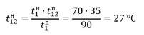
If the temperature of the coolant in the supply pipeline during setup of the system differs from the design one, then the following formula can be used for recalculation:
 where temperatures with index "P" -
design, and temperatures with the index “H” -
tuning (used for adjustment) values.
where temperatures with index "P" -
design, and temperatures with the index “H” -
tuning (used for adjustment) values.

Example
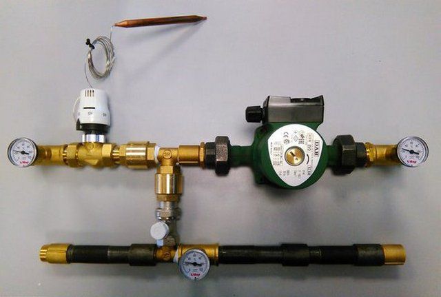
Consider the following heating system:
 To begin with, all balancing valves are closed.
The heating device that is furthest from the boiler is selected. IN in this case This is the rightmost radiator. The radiator balancing valve opens completely. After the radiator has warmed up, the temperature of the forward and return pipelines is recorded.
For example, after opening the valve, the temperature in the supply pipeline was 70 °C, the temperature in the return pipeline was 55 °C.
 Then a second device is taken at a distance from the boiler. The balancing valve on this device opens until the temperature in the return pipeline is equal to the temperature of the first ±5 °C.
 COMBIMIX setting: calculated flow temperature-
90 °C; design parameters of the heated floor circuit-
45-35 °C. Actual readings taken from thermometers: supply coolant temperature - 70 °C.
COMBIMIX setting: calculated flow temperature-
90 °C; design parameters of the heated floor circuit-
45-35 °C. Actual readings taken from thermometers: supply coolant temperature - 70 °C.
 Using the formula, we determine the temperature of the coolant in the supply pipeline of the secondary circuit:
 We determine the temperature of the coolant in the return pipeline of the secondary circuit:
 We open the balancing valve of the secondary circuit until the temperature on the thermometersCOMBIMIX
will not coincide with the calculated ones± 5°C.
We open the balancing valve of the secondary circuit until the temperature on the thermometersCOMBIMIX
will not coincide with the calculated ones± 5°C.
Fix the position of the shut-off valve using the adjusting screw (tighten the adjusting screw clockwise until it stops).
 After the adjusting screw is fixed, the valve can be opened and closed using a hexagon, the setting will not be lost.
 Bypass Valve Setting
There are two ways to set the bypass valve:
- If the resistance of the most loaded branch of the heated floor is known, then this value should be set on the bypass valve.
2. If the pressure loss on the most loaded branch is unknown, then the bypass valve setting can be determined from the pump characteristics.
The valve pressure value is set to 5-10% less than the maximum pump pressure at the selected speed. Maximum pressure pump is determined by the pump characteristics.
The bypass valve should open when the pump approaches a critical point, when there is no water flow and the pump works only to build up pressure. The pressure in this mode can be determined from the characteristic.

An example of determining the setting value of a bypass valve.
 In this example, it can be seen that the pump, in the absence of water movement at first speed, has a pressure of 3.05 m of water. Art. (0.3 bar), point 1
; at average speed - 4.5 m water. Art. (0.44 bar), point 2
; and at a maximum of 5.5 m water. Art. (0.54 bar), point 3
.
In this example, it can be seen that the pump, in the absence of water movement at first speed, has a pressure of 3.05 m of water. Art. (0.3 bar), point 1
; at average speed - 4.5 m water. Art. (0.44 bar), point 2
; and at a maximum of 5.5 m water. Art. (0.54 bar), point 3
.Since the pump is set to medium speed, we select the setting on the bypass valve 0.44 - 5% = 0.42 bar.
6. Final stage
After setting up all the components of the COMBIMIX unit, you should put back the thermal head of the control valve and make sure that the control valve is working. Close the cover of the primary circuit balancing valve. The unit is ready for use.
Setting up heating systems is one of the most difficult engineering tasks. The VALTEC COMBIMIX pump and mixing unit allows you to simplify this task. This unit is a ready-made comprehensive solution for organizing a heated floor circuit in heating systems. A well-thought-out configuration of the unit allows you to eliminate errors when designing a particular system. The flexibility of the unit setup allows you to set up underfloor heating systems without the use of special devices.
It is difficult to surprise anyone nowadays with a home heating system that operates on the principle of heating the floor surface. More and more owners of suburban housing, if they have not already switched, are seriously considering the prospects of switching to this effective and comfortable scheme for transferring heat from boiler equipment to the premises. One option is to organize water-heated floors. Despite the considerable complexity of their installation, they are very popular due to their economical operation, and due to their compatibility with an existing water heating system, of course, after certain modifications to the latter.
In general, start self-creation water “warm floors” without any experience in plumbing and general construction work is hardly worth it. Every nuance is important here - from the choice of pipes and their layout, from the correct thermal insulation of the floor surface and pouring the screed - to the installation of the hydraulic part with subsequent precise debugging of the system. But this is how the typical Russian home owner works: he wants to try everything himself. And if their hands are full, then many try to carry out such work on their own. To help them, this publication will discuss one of the most important components of such a system. So, what is it for, how is it designed, and is it possible to make a mixing unit for a heated floor with your own hands at home?
What role does the mixing unit play in a “warm floor” system?
The traditional heating system, which involves the installation of heat exchange devices in rooms (radiators or convectors), is a high-temperature one. This is exactly what it was designed for. absolute majority boilers of any type. The average temperature in the supply pipes in such systems is maintained at about 75 degrees, and is often even higher.
But such temperatures are absolutely unacceptable for “warm floor” circuits for a number of reasons.
- Firstly, it is completely uncomfortable to walk on a surface that is too hot and burns your feet. For optimal perception, temperatures in the range of 25÷30 degrees are usually sufficient.
- Secondly, not a single floor covering “likes” strong heating, and some of them simply quickly fail, lose their appearance, or begin to swell or develop cracks and cracks.
- Thirdly, high temperatures also negatively affect the screed.
- Fourthly, pipes of embedded circuits also have their own temperature limit, and given their rigid fixation in the concrete layer and the impossibility of thermal expansion, critical stresses are created in the pipe walls, leading to rapid failure.
- And fifthly, taking into account the area of the heated surface involved in heat transfer, high temperatures to create an optimal microclimate in the room are completely unnecessary.

How to achieve such “parity” of coolant temperatures in the system. There are, of course, modern boilers heating systems designed to work also with “warm floors”, that is, capable of maintaining the temperature in the supply pipe at 35-40 degrees. But what then to do with the fact that the house has both radiators and underfloor heating - organize two systems? It’s not profitable at all, it’s complicated, cumbersome, and difficult to manage. In addition, such boilers are still quite expensive.
It makes more sense to make do with existing equipment, simply making the necessary changes to the circuit layout. Optimal solution– mix the hot coolant with the cooled one, which has already given off heat to the premises, in order to reach the required temperature level.
By by and large, this is no different from the process that we go through many times every day, opening water tap, and by rotating the thumbs or moving the lever we achieve optimal temperature water for taking water procedures, washing dishes and other needs.

It is clear that the mixing unit itself is much more complex than a regular faucet. Its design must ensure stable, balanced circulation of coolant in the heated floor circuits, correct selection required quantity liquids from the supply and return pipes, the necessary “loop” of the flow (when there is no need for heat flow from the boiler), simple and clear visual control of the system parameters. Ideally, the mixing unit should itself, without human intervention, react to changes in the initial parameters and make the necessary adjustments to maintain a stable heating level.
This entire set of requirements, at first glance, seems very complex, difficult to understand, and even more so to implement independently. Therefore, many potential owners turn their attention to ready-made solutions– complete mixing units sold in stores. The appearance of such products really inspires respect with its “sophistication”, however, the price is quite often simply frightening.

But if you delve into the very principle of operation of the mixing unit, understand where, how and due to what the mixing process occurs, if you clearly imagine the direction of the coolant flows in it, then the picture becomes clearer. But in the end it turns out that to assemble such a unit by purchasing necessary details and using your editing skills sanitary products- quite a feasible task.
Let's make a reservation right away - in the future we will mainly talk about the mixing unit. It is subsequently connected to the “warm floor” collector, about which, of course, certain mentions are simply inevitable. But the collector itself, that is, its structure, principle of operation, installation, balancing - this is a topic for a separate publication, which will certainly appear on the pages of our portal.
Basic diagrams of mixing units for “warm floors”
There are a considerable number of schemes of mixing units for water-heated floors, differing in complexity, layout, saturation of monitoring and automatic control devices, dimensions and other characteristics. It is difficult to consider all of them, and there is no need to do so. Let us pay attention to those that are simple and understandable, do not require complex elements, and the assembly of which can be carried out by anyone with some knowledge of plumbing installation.
In all the diagrams below, the common pipes are located on the left heating circuit. The red arrow shows the entrance from the supply line, the blue arrow shows the exit to the return pipe.
WITH right side– connections of the pumping and mixing unit with the “combs”, that is, with the underfloor heating manifold, also indicated by red and blue arrows. It should be understood that the “combs” of the collector can be attached directly to the unit or placed at a certain distance and connected by piping - it all depends on the specific conditions of the system. Often circumstances develop in such a way that the mixing unit is located in the area of the boiler room, and the collector is already moved into the room, to the place from which it is most convenient to lay out the “warm floor” circuits. This does not change the essence of the operation of the pumping and mixing unit.
Translucent arrows of red and blue shades the directions of movement of coolant flows are shown.
Scheme 1 – with a two-way thermal valve and a series connection of a circulation pump
One of the simplest mixing unit designs to implement. To begin with, look at the drawing.

Let's look at the components:
- Pos. 1 – these are shut-off ball valves. Their task is only to completely shut off the pumping and mixing unit if necessary, for example, when there is no need for floor heating, or when certain maintenance and repair work is required.

None special requirements, except for the high quality of products, is not required for cranes. They perform exclusively the role of shut-off valves, and do not take any part in regulating the operation of the heating system. In principle, only two positions should be used on them - fully open or fully closed.
Cranes pos. 1.1 and 1.4, which cut off the entire underfloor heating system from the general heating circuit, are mandatory. Cranes pos. 1.2 and 1.3 - can be placed between the mixing unit and the manifold at the discretion of the master, but they will never interfere. It becomes possible to cut off the collector unit for carrying out any work without covering the actual contours of the heated floor, that is, without disrupting the adjusted settings of each of them.
- Pos. 2 – coarse filter (so-called “oblique” filter). It probably cannot be called an absolutely essential element of the mixing unit, but it is inexpensive and can affect the longevity of the system.

It is clear that such filtering devices are required to be installed in a common boiler room. However, when the coolant circulates in a branched system, it cannot be ruled out that solid inclusions will enter it and be transferred, for example, from heating radiators. And the pumping and mixing units and the following manifold units are saturated with control elements for which solid impurities are extremely undesirable, since they can destabilize the operation of valve devices. This means that it would be wiser to supplement your mixing circuit with an individual filter.
- Pos. 3 – thermometers. These devices help to visually monitor the operation of the mixing unit, which is especially important when debugging and balancing the “warm floor” system. All subsequent diagrams will show three thermometers - on the supply pipe from the common circuit (pos. 3.1), at the inlet to the manifold, that is, showing the temperature of the flow after mixing (pos. 3.2), and on the “return” after the manifold, before the branch from it to the mixing unit (pos. 3.3). This is probably the optimal location, clearly showing both the quality of mixing and the degree of heat transfer of the “warm floor”. Ideally, the difference in readings on the supply and return manifold combs should not be higher than 5÷10 degrees. However, some craftsmen make do with fewer thermometers.

The design of thermometers may vary. Some people prefer overhead models that do not require insertion into the system (in the illustration on the left). But devices with a probe sensor, which is screwed into the corresponding socket of the tee, still have greater accuracy of readings, and simply reliability.
- Pos. 4 – two-way thermal valve. This is exactly the same element as is installed on heating radiators. In this scheme, it is he who will quantitatively regulate the flow of hot coolant entering the “warm floor” system.

There is one nuance here - such thermal valves differ in purpose - for single-pipe or two-pipe systems heating. But this difference is important when installing them on a separate radiator. But for a mixing unit that serves several “warm floor” circuits, increased productivity is important. This means that you should choose a valve for single-pipe systems, even if the entire system is organized on a two-pipe principle. These valves are even visually larger in size; they are usually marked with the letter “G” and are distinguished by a gray protective cap.
- Pos. 5 – thermal head with a remote patch-on sensor (item 6). This device is put on (screwed on or secured with a special adapter) onto the thermal valve and directly controls its operation. Depending on the temperature readings on the remote sensor, which is connected to the head by a capillary tube, the valve will change position, slightly opening or completely blocking the passage for the hot coolant.

Prices for thermal head
Thermal head
Immediately the question is - where to install the temperature sensor? There are two options - it can be applied to the supply pipe to the manifold, after the mixing unit, behind the pump, or on the return pipe of the manifold, before it branches into mixing. There are adherents of both methods.
— In the first case, a constant temperature of the coolant supply to the heated floor circuits is ensured. Stable operation is ensured and the likelihood of floor overheating is reduced to almost zero. But, at the same time, the system, if it is not additionally equipped with thermostatic elements directly on the circuits, ceases to respond to changes in external conditions. That is, a change in the temperature in the room will not in any way affect the heating level of the coolant supplied to the “warm floor”.
You might be interested in information about how to do it yourself
— In the second case, with a temperature sensor on the return, temperature stability is ensured in this particular area. That is, the heating level of the coolant entering the collector after the mixing unit may fluctuate. This scheme is good in that the system responds, for example, to cold weather, automatically raising the supply temperature and lowering it when it warms up. Convenient, but there are certain risks. So, during the initial heating of the floor screed, too hot coolant may initially flow into the circuits. A similar situation is quite likely with a sudden influx of cold, for example, with windows wide open in case of emergency ventilation of the room.
Changing the position of an overhead temperature sensor is not so difficult if you provide places for its installation in advance. So you can try both options and then choose the optimal one.
We will not talk about the design of the thermal valve and thermostatic head - there is a separate publication on this topic.
How does the thermostatic control system for heating radiators work?
Installing additional devices allows you to ensure constant comfortable conditions in the room, regardless of changes in external conditions. Purpose, device, installation and operation are in a special article on our portal.
- Pos. 7 - ordinary plumbing tees, between which a kind of bypass is laid - a jumper, through which the coolant will be taken from the “return” for mixing with the hot flow. In fact, the 7.1 tee becomes the main mixing zone.
- Pos. 8 – balancing valve. It is used to fine-tune the system in order to achieve optimal readings of the circulation pump in terms of pressure and performance. It may be necessary to reduce (or, as plumbers often say, “strangle”) the flow through the return jumper so that unnecessary areas of excessive vacuum or high pressure are not created in various areas of the mixing unit and manifold, and the pump itself operates in optimal mode.

There are no tricks in this device - in fact, it is an ordinary valve that limited the flow. You can also install an ordinary plumbing valve here. The block crane shown in the illustration is more advantageous from the point of view that it is compact, and also because no one can accidentally knock down the settings made with a hex key, for example, children who simply want to turn the flywheel out of curiosity. So it’s better, after setting up the system, to close the adjustment unit with a lid - and be relatively calm.
- Pos. 9 - circulation pump. The pump that services the entire heating system as a whole will not be able to provide circulation through long “warm floor” circuits, especially if several of them are connected to the collector. So each mixing unit is equipped with its own device.

Setting up a heated floor system will be easier if the circulation pump has several switchable operating modes.
Circulation pump prices
circulation pump
How to choose the right circulation pump?
The variety of models nowadays is extremely large, which can even confuse an inexperienced consumer. More details about the device and the rules for their selection and installation can be found in a special publication on our portal.
- Pos. 10 - check valve. A very simple and inexpensive plumbing fixture that prevents unauthorized flow of coolant in the opposite direction

It could seem. That there is no special need to install it. However, such insurance may not be superfluous. For example, a situation where the thermal valve, due to sufficient temperature on the manifold, is completely closed. The circulation pump works and, in principle, is capable of sucking coolant from the common “return” pipe of the system. And there the temperatures are completely different, much higher than even at the “warm floor” supply. That is, such a reverse current can greatly disorient the operation of the mixing unit.
With the elements and their mutual arrangement - everything. Let's see how such a node works.
The coolant flow from the common supply pipe bypasses the “oblique” filter and thermometer and reaches the thermostatic valve. Here it decreases due to a decrease in the lumen of the channel for the free passage of liquid. The thermal head closely monitors the dynamics of temperature changes, slightly opening or closing the valve device.
The circulation pump operating in the “warm floor” circuit leaves behind a vacuum zone, which “draws in” the regulated flow of hot coolant. But since the pump performance does not change, the “shortage” is compensated by the flow of cooled coolant from the return line coming from the collector through the bypass jumper.
You may be interested in information about how to equip
At the point of connection of the flows (in the upper tee), their mixing begins, and the pump pumps the already brought to desired temperature coolant. If the temperature at the thermal head sensor is sufficient or excessive, then the thermal valve will be closed altogether, and the pump will begin to drive water only along the “warm floor” circuits, without external replenishment, until it cools down. As soon as the temperature drops below the set value, the thermal valve will slightly open the passage of the hot coolant to reach the required value after the mixing point.
With stable operation of the system, brought to its design capacity, the flow of hot coolant from the general supply is usually not so large. The valve is mostly in a slightly open state, but at the same time it reacts very sensitively to changes in external conditions, ensuring temperature stability in the “warm floor” circuits.
A similar principle, in which the entire volume of coolant pumped by the circulation pump is sent to the “warm floor” collector, is called a mixing unit with a series connection of the pump.
Scheme 2 - with a three-way thermal valve and a series connection of a circulation pump
This scheme is very similar to the previous one, however, it also has its differences.

The main difference is the use of not a two-way, but a three-way thermal valve (item 11) with the same thermostatic head. It took the place of the tee at the intersection of the supply line and the bypass jumper pipe.

In this case, mixing takes place directly in the thermal valve body. It is designed in such a way that when one coolant supply channel is closed, the second one is simultaneously opened slightly, which ensures greater stability of the mixing unit - the total flow rate is always maintained at the same level. This makes it possible to do without a balancing valve on the bypass.
Important - three-way thermal valves come in mixing and separating operating principles. In this case, what is needed is a mixing one, with perpendicular flow directions. Usually the corresponding arrows are placed on the body of the device, and it is difficult to make a mistake with this.

A three-way valve can be made without a thermal head - with its own built-in temperature sensor and a scale for setting the required outlet temperature. Some craftsmen prefer just this, thermostatic variety, as it is easier to install. True, a device with a remote sensor still works more accurately. In addition, when operating a system with a thermostatic three-way valve, there is a higher probability of unauthorized passage of coolant high temperature to the collector.

Three-way separating valves, by the way, can also be used in a similar scheme. Only their installation location is on the opposite side of the bypass, and they already regulate the separation and redirection of the flow of cooled coolant to the mixing point, towards the pump.

A mixing unit with a three-way valve, due to its high stable performance, is more suitable for large collector junctions with several circuits of varying lengths. They are also used in the case of using weather-dependent automation, which often also involves automated control of the operation of the circulation pump. For small systems it does not justify itself, as it is more difficult to adjust.
The diagram below the question mark shows a check valve (pos. 10.1). In principle, it is justified if for one reason or another the circulation pump of the unit does not work, for example, the automation gave a command to stop circulation. In such situations, the jumper from the return to the three-way valve can turn into a completely uncontrollable bypass, which will upset the balance of the system and affect the operation of other heating devices in the house. A check valve can prevent this phenomenon. However, many experienced craftsmen they question the likelihood of such situations occurring, and consider the valve in this area to be completely unnecessary and even harmful, as providing unnecessary hydraulic resistance.
Three way valve prices
three way valve
Scheme 3 - with a three-way thermostatic valve operating with converging flows and a series connection of a circulation pump
You can find it on sale thermostatic valves, which are organized according to the principle of mixing two flows converging along one axis. With them, the assembly diagram of the pumping and mixing unit can take the following form:

It is not difficult to distinguish such thermostatic taps by their characteristic shape and printed diagrams (pictograms) of the direction of flow.

The circuit shown above is good for its compactness. There is no bypass at all, as its role is completely performed by the mixing valve itself. Otherwise, this is the same circuit with the principle of connecting a circulation pump in series.
Scheme 4 - with a two-way thermal valve and parallel connection of a circulation pump
But this scheme is already significantly different from all those shown above:

This principle of unit structure involves the so-called parallel connection of the pump, literally on the bypass. But two meeting flows approach the upper point of this bypass - from the supply common system and from the collector return. A two-way thermal valve with a thermal head and a remote sensor is installed on the supply - everything is the same as in the first scheme. The pump providing circulation through the jumper takes both converging flows, and their mixing occurs in the tee at the top (highlighted by an oval and an arrow) and in the pump itself. But further, at the lower point of the jumper on the tee, the flow is divided. Part of the coolant with the temperature already leveled to the required level is sent to the supply manifold of the “warm floor”, and the excess amount is discharged into the general “return” of the heating system.
This scheme attracts, first of all, its compactness. In conditions of limited space for installing a mixing unit, this is one of the acceptable solutions. However, it has many shortcomings. First of all, it is obvious that its performance is clearly inferior to units with a series pump connection. It turns out that a certain volume of coolant, after mixing and bringing it to the required temperature, is pumped by the pump in vain - it does not participate in the operation of the heated floor circuits and simply goes into the “return”.
In addition, such a system is quite difficult to balance, and often requires the installation of additional balancing and (or) bypass valves.
It is interesting that many ready-made factory-assembled mixing units are organized in a parallel circuit - most likely for reasons of maximum compactness. And craftsmen are coming up with ways to convert them into a more “obedient” circuit - with a series pump.
Warm floors rehau (rehau) are one of the leaders among similar heating systems. If you choose and install correctly suitable option, you can provide a comfortable atmosphere in the rooms and for a long time Don't worry about heating the room.
Additional equipment for heated floors Rehau
heated floors will make the kitchen more comfortable
Included with the basic materials for installing heated floors are additional elements that are used when installing the structure.
RAUFIX tires
Installation of heated floor:
Care and instructions for use

Caring for a heated floor is not too labor-intensive, but since the entire system is located in the depths.
After correct installation underfloor heating and installation flooring you need to wait a while, and then you can safely walk on the floor and install even fairly heavy household items on it, since Rehau systems are reliable and have a high hardness rating. You can read about materials for warm water floors.

Choose the right flooring
You should avoid the possibility of causing damage to the structure of the heating system, and carefully operate free-standing elements, such as control units and other important equipment. If possible, it is necessary to prevent children from having access to devices used to monitor and control the supply of water and its heating in order to avoid sudden temperature changes.
If necessary, maintenance should be carried out and timely repairs designs. Usually these actions are carried out by a competent master. Care warm floors Rehau is not important. Floor coverings should be kept clean and in good condition. The entire system is recessed into the floor, so the most important action required from users is to be careful during operation. We also recommend that you familiarize yourself with the technology of installation, laying and installing a warm water floor.
For and against underfloor heating, watch the video:
It is one of the leaders on the market of similar systems, as it is distinguished not only by its outstanding performance characteristics and ease of use, but is also quite economical, since it does not leave waste during installation and requires virtually no repairs. If installed correctly, you can enjoy comfortable and reliable heating for a long time.
Comfort in the home is one of the most important components of arranging your own home. It's not only cozy atmosphere and modern technology, but also high-quality ventilation, and most importantly warm and good climate. It is this point that deserves special attention.
Modern technologies offer wide possibilities for heating a home, and along with traditional central heating The “warm floor” system is increasingly being used. Do-it-yourself mixing unit for heated floors is just part of the work you will have to do.
The collector is a kind of connecting pipeline that distributes the coolant in various heating systems. In simple words, it is just a pipe that can connect and connect other pipelines.
On all similar types of connections, threads are applied on both sides: external and internal. The price of such a device depends on the manufacturer and configuration.
IN heating system for heated floors, the coolant is supplied to the manifold, with the help of which it is distributed over all loops. After this, the coolant moves to the return collector, which directs it to the boiler for heating. The process repeats again.
Diagram and principle of operation of the mixing unit
The mixing unit includes a pump and a valve. But more advanced configurations are also often found.
The circulation pump may be located on the boiler itself, but its power will not be enough. For heated floors, it is necessary to install a separate pump on the mixing unit. In this way, the temperature will be freely regulated and reduced from 70–90 °C to 35–50 °C.
In addition, the mixer must have a fuse that turns off the pump as soon as the supply temperature exceeds the set one.

The water reaches 85 °C in the supply pipe. Legend:
- Three-way valve;
- Pump;
- Temperature sensor;
- Check valve.
The return flows from the collector. The coolant temperature in it is 40 °C. There is a check valve on it that prevents the backflow of water.
Thus, when the thermostatic device is triggered, the damper automatically opens, thereby mixing more cold water from the return line. After the temperature normalizes, the damper closes.
Two-way mixing unit
A two-way or feed mixer works on the principle described above. After the thermal head is triggered, it cuts off the hot water supply and mixes in return water. The floor does not overheat, thereby increasing its service life.
This type of mixing unit has a small throughput, so the supplied water is adjusted smoothly, without jumps. Most craftsmen prefer this type of mixer. But, unfortunately, it is not suitable for heating areas larger than 200 m².
Three-way valve
Plays the role of a throughput valve while also performing the functions of a bypass valve. But, unlike him, inside the three-way is mixed hot water with cold return. As a rule, such devices are equipped with thermostats.
Inside, between the return and supply pipes, there is a damper. By opening or closing it, the water supply is regulated.
Do-it-yourself installation and installation of a mixing unit for heated floors

Due to the high cost of ready-made equipment for heated floors, the profitability of assembling such equipment yourself is quite high. Unfortunately, not everyone will be able to cope with this task, but further information will be useful in any case. So, the material you will need for installation:
- union nuts;
- nipples;
- air vent (manual);
- thermometers;
- check valve;
- circular pump;
- tees; Various types connections, etc.
The assembly technology consists of installing thermometers installed in the supply and check valves. Their task is to control the degrees of transported liquid. The operating principle of the remaining elements of the circuit has already been described earlier.

The pump, due to circulation, will support the process of heating water in the pipeline. By installing a bypass, the system will be protected from overheating. The water drain valve, in turn, will protect the pipes from rupture in case of excess pressure.
After completing the assembly of the unit, it is connected to the circuits using fittings. But before you start the system, you need to balance it.
Installation features:

- The assembled or factory mixing unit is mounted to the contour of the heated floor.
- Installation can be either left- or right-handed.
- The knot can be attached in a special locker, in the room itself or in a specially designated room (boiler room).
- First install the pump and a temperature sensor.
- A mixing valve is connected to the supply pipe (“warm”), and a warm valve is connected to the return pipe.
- Balancing is done using test inclusions: at high or low temperatures, it is reduced/increased accordingly until it is normalized.
The heated floor is connected according to the diagram below. However, each connection case has its own characteristics. For example, when single pipe system, the bypass must be constantly open, but with a two-pipe system this is not necessary.

Connection diagrams differ in the presence and absence additional elements, but this is not so important. The main thing is to know that valves, flow meters and thermostats must be installed on each group of manifolds.
One of the know-how technologies is weather-dependent controllers. Thanks to them, the temperature of the heated floor is automatically adjusted depending on the weather outside. Special sensors measure every 20 seconds how many degrees it is outside and, based on this, they shift or do not shift the temperature of the heated floor by 4.5 °C.
To conclude the instructions, I would like to add a video that shows all the intricacies of installation:
Advantages of underfloor heating with a mixing unit:
- Long service life. The only element in the system that is more susceptible to wear than others is the pipe. Its minimum wear resistance period is 50 years.
- Automated control, due to weather-dependent thermostats. The heating level is adjusted depending on how cold it is outside at the current time.
- Possibility of use manual mode . Suitable for those who prefer to regulate the temperature with their own hands.
- Inability to overheat the system and burst pipes, thanks to the presence of thermostat sensors and special valves.
- Economical. When installing the system yourself, you can save a lot of money.
Read how to choose high-quality pipes for heated floors at
- why are they needed, how to choose, how to install.
A correctly calculated underfloor heating will not only allow you to install the system more efficiently, but will also save money on materials. all the necessary formulas.