A beautiful enameled stove means a beautiful enameled chimney.
Is it possible to install stainless steel?
New Product
These enameled chimneys are coated with a special composition of high heat resistance and acid resistance. The enamel can withstand very high flue gas temperatures.
For example, modular chimney systems "LOKKI" produced by the Novosibirsk plant "SibUniversal" have the following data:
- The operating temperature of the chimney is 450°C, a short-term increase in temperature up to 900°C is allowed.
- Able to withstand temperatures stove fire» 1160°C for 31 minutes. Although the standard is 15 minutes.
Flue gas temperature
In the table we have collected the temperature indicators of the exhaust flue gases of different heating devices.
After comparison it becomes clear to us that operating temperature of enameled chimneys 450°C is not suitable for Russian wood-burning stoves and fireplaces, wood-burning sauna stoves and coal boilers, but this chimney is quite suitable for all other types of heating appliances.
In the descriptions of the chimney systems "Locky" it is directly stated that they are intended for connection to any type of heating devices with an operating temperature of exhaust gases from 80°C to 450°C.
Note. We love to heat up the sauna stove until it's red hot. Yes, even for a long time. This is why the temperature of the flue gases is so high, and this is why fires occur so often in bathhouses.
In these cases, especially in sauna stoves, you can use a thick-walled steel or cast iron pipe as the first element after the furnace. The fact is that the main part of the hot gases is cooled to an acceptable temperature (less than 450°C) already on the first element of the pipe.
What is heat-resistant enamel?
Steel is a durable material, but has a significant drawback - it is prone to corrosion. To ensure that metal pipes can withstand adverse conditions, they are coated with protective compounds. One of the options protective composition is enamel, and since we're talking about about chimneys, the enamel must be heat-resistant.
Please note: enameled chimneys have a two-layer coating, metal pipe coated first with primer and then with top enamel.
To give the enamel the necessary properties, special additives are introduced into the molten mixture during its preparation. The base of the ground and top enamel is the same; a melt from:
- Quartz sand;
- Kaolina;
- Potash and a number of other minerals.
But different additives are used for top and base enamel. Metal oxides (nickel, cobalt, etc.) are introduced into the soil composition. Thanks to these substances, reliable adhesion of the metal to the enamel layer is ensured.
Titanium and zirconium oxides, as well as fluorides of some alkali metals, are added to the coating enamel. These substances provide not only increased heat resistance, but also the strength of the coating. And to give the coating decorative properties in the process of preparing the coating enamel, colored pigments are introduced into the molten composition
Pipe material

Attention. Lightweight thin-walled metal and mineral wool allows you to do without installing a special foundation for the chimney system. The pipes are mounted on brackets on any wall.
Equipment
In the double-wall version, the space between the pipes is filled with mineral (basalt) wool, which is a non-flammable material with a melting point of more than 1000 degrees.
Manufacturers and suppliers of enameled chimney systems offer a wide range of components:
- Pipes are double-circuit and single-circuit.
- Branches are double-circuit and single-circuit.
- Tees.
- (latches) rotary with fixation.
- Roof cuttings - units for the passage of the roof.
- Ceiling grooves - units for the passage of the ceiling.
- Umbrellas.
- Headings.
- Plugs.
- Flanges, including decorative ones.
- Protective screens.
- Fasteners: clamps, brackets, cleaning windows.
Installation
In any case, we begin to install the chimney “from the stove”, from heating device, that is, from bottom to top.
- The inner tube of each subsequent element goes inside the previous element. This prevents condensation or atmospheric precipitation on basalt insulation. A outer pipe, which is often called a shell, is put on the previous pipe.
- According to the requirements of fire safety standards, the pipe fit (depth of the nozzle) must be at least half the diameter of the outer pipe.
- The joints are sealed with clamps or mounted on a cone. This is determined by the manufacturer of the design. For reliable sealing, there are sealants with an operating temperature of 1000°C.
- The joints of pipes with tees or bends must be secured with clamps.
- Wall mounting brackets are installed at least every 2 meters.
- Each tee is mounted on a separate support bracket.
- The chimney route should not have horizontal sections of more than one meter.
- In areas where walls, ceilings and roofs pass through, it is necessary to use elements that meet fire safety requirements.
- Chimney routes should not come into contact with gas, electricity and other communications.
Reasonable care must be taken during installation work. It is recommended to use only rubberized tools, this will avoid damaging the integrity of the pipe coating (chips, cracks). This is very important, since in the place where the enamel is damaged, a corrosion process begins to develop, destroying the pipe.
In general, we can say that such chimneys have undoubted aesthetic advantages compared to stainless ones. But there are no technical, operational or installation advantages.


 Pipe destruction often occurs due to the use of low-quality bricks (a, b). Moisture-resistant cladding can protect the masonry (c). Sand-lime brick unsuitable for the construction of chimneys (d)
Outside the window - dank autumn evening, and the fire is burning brightly in the fireplace, and the room is filled with a very special warmth... For this country idyll to become a reality, you need a competently designed and installed chimney, which, unfortunately, is often the last thing remembered.
The degree of reliability and efficiency of chimneys largely depends on the heating devices connected to them, and vice versa. Therefore, for each type of fireplace there is best option chimney.
Very different fireplaces

And finally, the last type is fireplace stoves. home distinguishing feature similar devices, giving them a resemblance to real oven, - the presence of a built-in smoke channel, passing through which the flue gases are cooled to a fairly low temperature. In this regard, there is a need for a massive masonry or well-insulated modular chimney.

Make way for smoke!

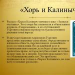
Ethnographic touches
The houses of Korean settlers in the Ussuri region were equipped with very exotic chimneys. This is how V.K. Arsenyev described them: “Inside... there is a clay canal. It occupies more than half of the room. Chimney pipes run under the canal, warming the floors in the rooms and distributing heat throughout the house. The smoke ducts are led outside into a large hollow tree that replaces the chimney.”
Some peoples of the Volga region and Siberia until the 30s. XX century Chuval was widespread - a wall-mounted open hearth with a straight chimney hanging over it. The hearth was made of stones or logs covered with a layer of clay, and the chimney was made of hollow wood and thin poles coated with clay. In winter, the chuval was heated all day, and the pipe was plugged at night.
Brick chimneys until recently, there were practically no alternatives in both urban and rural construction. Being a universal structural material, brick allows you to vary the number of chimney channels and the thickness of the walls (you can make the necessary thickenings in the places where the floors and roofs pass, as well as when constructing the street part of the chimney). If construction technologies are followed, a brick chimney is very durable. However, it also has disadvantages. Due to the significant mass (pipe with a cross-section of 260
To install a brick chimney, very highly qualified builders are required. What are the most common mistakes during its construction? This is the choice of low-quality or unsuitable bricks (weakly fired partition or wall); thickness of masonry joints more than 5 mm; edge laying; the use of stepped (“toothed”) masonry on sloping areas; improper preparation of the solution (for example, if the ratio of the parts of clay and sand is chosen without taking into account the fat content of the clay), careless splitting or cutting of bricks; inattentive filling and bandaging of masonry seams (presence of voids and double vertical seams); laying pipes close to structures made of combustible materials.
The condition of the brick pipe requires constant monitoring. Previously, it was certainly whitewashed, since on a white surface it is easier to notice soot, indicating the presence of cracks.
Expert opinion
The brick chimney has faithfully served man for centuries. Laying stoves and fireplaces from this material is almost an art. The paradox is that during the period of mass dacha construction in our country, this skill suffered serious damage. The consequences of the “work” of numerous unfortunate stove-makers were sad, and most importantly, they gave rise to distrust of brick fireboxes and chimneys. Therefore, favorable conditions have arisen and continue to exist for the promotion of factory-ready chimney systems to the domestic market.
Alexander Zhilyakov,
Head of the wholesale department of the Saunas and Fireplaces company
Stainless steel pipes can safely be attributed to the most widely used type of chimney today. Steel modular systems have a number of undeniable advantages. The main ones are light weight, ease of installation, a wide selection of pipes of different diameters and lengths, as well as shaped elements. Steel chimneys are manufactured in two versions - single- and double-circuit (the latter - in the form of a “sandwich” of two coaxial pipes with a layer of non-flammable thermal insulation). The first ones are intended for installation in heated rooms, connecting a fireplace to an existing chimney, as well as sanitizing old brick pipes. The second ones are ready-made constructive solution, equally suitable for installing a chimney both inside and outside the building. Special view smoke channels made of stainless steel - flexible single- and double-walled (without thermal insulation) corrugated hoses.
For the production of single-circuit chimneys and internal pipes of sandwich-type chimneys, alloyed heat- and acid-resistant sheet steel (usually 0.5-0.6 mm thick) is used. Single-circuit chimneys made of carbon steel, coated outside and inside with special black enamel (such are available, for example, in the range of Bofill, Spain), are even superior to stainless steel pipes in heat resistance; They are also not afraid of condensation, but only if the coating is intact, which is easily damaged (say, when cleaning a chimney). The service life of uncoated pipes made of “black” steel with a thickness of 1 mm does not exceed 5 years.
The casing (shell) of sandwich pipes is usually made of ordinary (non-heat-resistant) stainless steel, which is polished electrochemically to mirror shine, and some manufacturers, such as Jeremias (Germany), offer enamel painting in any color on the RAL scale. The use of a galvanized steel casing is justified only when installing a chimney inside a building. From the outside, such a pipe, if the chimney is actively used, will not last long: due to periodic heating, corrosion intensifies.
Expert opinion
Stainless steels used for the production of chimneys are divided into two categories: magnetic ferrite (in the American ASTM standardization system these are AISI 409, 430, 439, etc.) and non-magnetic austenitic (AISI 304, 316, 321, etc.). ). According to our tests of AISI 409 steel (composition: 0.08% C, 1% Mn, 1% Si, 10.5-11.75% Cr, 0.75% Ti), the critical temperature value in the inner pipe of the insulated chimney fragment , at which the effect of intercrystalline corrosion became noticeable, was equal to 800-900
Alexey Matveev,
Head of the commercial department of the company "NII KM"
The thermal insulation layer in sandwich pipes solves three problems at once: it prevents overcooling of flue gases from negatively affecting draft, does not allow the temperature of the internal walls of the chimney to drop to the dew point, and, finally, ensures a fire-safe temperature of the external walls. The choice of insulating materials is small: usually it is basalt wool (Rockwool, Denmark; Paroc, Finland) or silicone wool (Supersil, "Elits", both - Russia), perlite sand (but it can only be filled in during the installation of the chimney).
Such a very important characteristic of a chimney as gas tightness depends on the design of the pipe joints, so every manufacturer strives to bring it to perfection. Thus, sealing of the Hild chimney (France) is provided by centering couplings; The double annular protrusion formed at the joint is crimped with clamps included in the delivery of each module. Raab chimneys have a cone-shaped connection in combination with a ring lip. In Selkirk systems (Great Britain), high gas density can be achieved due to the special design of the clamp. The vast majority of stainless steel chimneys are installed in the traditional way, and here a lot depends on the quality of the parts. Typically, the upper module is put on the lower one, but single-circuit, and when laying externally, double-circuit modules should be joined by inserting the upper one into the lower one, which will avoid condensate leakage through the joints.
Chimneys for fireplaces with different characteristics
| Fireplace type | Combustion feature | Efficiency, % | Temperature of exhaust gases, | Chimney type |
|---|---|---|---|---|
| With open firebox | Air access is not limited | 15-20 | Up to 600* | Brick, heat-resistant concrete |
| With closed firebox | Air access may be limited | 70-80 | 400-500 | Brick, made of heat-resistant concrete, modular insulated from stainless steel or ceramic, within heated premises - single-circuit enameled steel |
| Fireplace stoves | Air access is limited, gases are cooled passing through integrated channels | Up to 85 | 160-230** | In addition to those listed above: soapmagnesite or soapchlorite - massive or with an internal pipe (steel, ceramic) |
* - when using hardwood, coal as fuel, as well as with excess draft, the temperature may exceed the specified value;
** - for fireplace stoves made of soapstone; for metal - up to 400
Ceramic chimneys- these are the same “sandwiches”, but “cooked” according to a completely different recipe. The inner tube is a pottery product made of fireclay mass, the middle layer is unchanged basalt wool, external - sections from lightweight concrete or mirror stainless steel. Such systems are presented on the domestic market by the company Schiedel (Germany).
Ceramic chimneys are resistant to high temperatures (up to 1000
Ceramic systems also have their disadvantages. Chimneys with a concrete casing have a significant mass (1 linear meter weighs from 80 kg), can only be used as main ones (free-standing), and do not allow obstacles to be bypassed. The “weak link” of such chimneys is the connection point. Manufacturers provide for the use of a metal module (modules), which has a shorter service life and therefore will require replacement in the future, which must be taken into account when building a fireplace.


Raab chimneys with stainless steel inner pipe and concrete casing:
with ventilation duct(s)
or without it (b)
And finally, metal does not combine well with ceramics because it has a high coefficient of thermal expansion: around the perimeter of the steel pipe where it enters the ceramic one, it is necessary to leave a fairly large (about 10 mm) gap, which is filled with asbestos cord or heat-resistant sealant.
However, the high reliability and durability of ceramic chimneys (the factory warranty is 30 years, and the actual service life, according to manufacturers, is more than 100 years) allows us to turn a blind eye to the listed shortcomings. Moreover, the price of Schiedel products is quite comparable to the cost of imported stainless steel systems - only the set of the first three meters of the chimney, including a condensate collector, inspection, connection unit and damper, is relatively expensive. For example, a 10 m high chimney of the Uni system with ceramic pipes with a diameter of 200 mm without a ventilation duct costs about 43 thousand rubles.
Comparative cost of a dual-circuit stainless steel module 1000 mm long, rub.
| Firm | A country | Thermal insulation thickness, mm | Price (depending on diameter, mm) | ||
|---|---|---|---|---|---|
| 150 | 200 | 250 | |||
| Selkirk, Europa model | Great Britain | 25 | 6100 | 7500 | 9100 |
| Jeremias | Germany | 32,5 | 3400 | 4300 | 5700 |
| Raab | Germany | 30 | 4450 | 5850 | 7950 |
| Hild | France | 25 | 2850 | 3300 | 5100 |
| Bofill | Spain | 30 | 3540 | 4500 | 5700 |
| "Elites" | Russia | 30 | 3000 | 3480 | 4220 |
| "NII KM" | Russia | 35 | 2235 | 2750 | 3550 |
| FineLine | Russia | 30 | 2600 | 3410 | 4010 |
| "Baltvent-M" | Russia | 25/50 | 2860/3150 | 3660/4030 | 4460/4910 |
| "Inzhkomcenter VVD" | Russia | 25 | 1600 | 2000 | - |
| Rosinox | Russia | 25/50 | 2950/3570 | 3900/4750 | 4700/5700 |
| "Salner" | Russia | 35 | 2550 | 3100 | 4100 |
| "Volcano" | Russia | 50 | 3050 | 3850 | 4550 |
| "Deluxe version" | Russia | 35 | 2600 | 3350 | 4120 |
How many pipes is just right?
The question of the possibility of connecting two fireplaces to one chimney is controversial. According to the requirements of SNiP 41-01-2003, “for each stove, as a rule, a separate chimney or channel should be provided... It is allowed to connect two stoves located in the same apartment on the same floor to one chimney. When connecting chimneys in them cuts should be provided (middle walls dividing the chimney into two channels. - Ed.) with a height of at least 1 m from the bottom of the pipe connection." As for the cutting, it can only be done in a brick chimney. If the chimney is modular, it is enough to use a tee to connect the pipe of the second firebox to the pipe of the first (if the smoke channels have different diameter, then the smaller one is cut into the larger one), after which it is necessary to increase the cross-section of the channel. How much? Some experts believe that if simultaneous operation of the furnaces is planned, then the cross-sectional area is determined by simple summation. Others believe that it is enough to “throw on” 30-50%, since two fireboxes will better warm up the common pipe and the draft will increase, but this only applies to chimneys with a height of more than 6 m.
When connecting two stoves located on different floors to one chimney, everything is much more complicated. Practice shows that such systems work, but only with careful calculation and numerous additional conditions (increasing the height of the chimney, installing dampers after the lower firebox and on the inlet pipe of the upper one, observing the firing order or completely eliminating simultaneous operation, etc.).
Please note that everything said in this section applies only to fireplaces with a closed firebox. An open firebox is more fire hazardous and requires draft, so it does not allow any “liberties” and requires the construction of a separate chimney.
On the street with a pole, in the hut with a tablecloth
Poor draft usually occurs due to errors in the design of the chimney. The desire to explain it as unfavorable weather conditions(differences atmospheric pressure and air temperature) is unreasonable, since a competent decision takes into account these factors. Let us list the reasons for poor traction and its periodic overturning (that is, the occurrence of reverse traction):
It is much more difficult to determine the cause in each specific case, since several factors often act at once, none of which plays an independent role. To improve draft, it is necessary to change the design of the chimney, sometimes not too significantly (for example, increase the thickness of the thermal insulation on the last one and a half to two meters of the pipe). There is also such a problem as excess traction. You can deal with it using a gate. You just need to provide for its installation before starting the installation of the chimney.

There is no smoke without... water
The main gaseous products of combustion of carbon-containing fuels are carbon dioxide and water vapor. In addition, during combustion, the moisture present in the fuel itself (wood) evaporates. As a result of the interaction of water vapor with oxides of sulfur and nitrogen, vapors of low concentration acids are formed, condensing on the inner surface of the chimney when they are cooled to a temperature below critical (when burning wood - about 50
If you heat a fireplace with an external uninsulated fireplace in the cold season metal chimney, the amount of condensate can be measured in liters per day. A brick pipe is capable of accumulating heat, so it behaves differently: condensation forms only at the stage of heating the pipe (although this is a rather long period of time). In addition, the material partially absorbs condensation, so the latter is not too noticeable, which, however, does not prevent it from having a destructive effect on the masonry. If the burning intensity is low and the ambient temperature is low, the brick may cool down and condensation will begin to form again. If the thickness of the insulation is insufficient and the temperature of the exhaust gases is low (the firebox is adjusted for long-term combustion), condensation can also appear in a modular chimney of the “sandwich” type. One way or another, it is impossible to completely get rid of condensate; you just need to reduce its amount to a minimum (the main means for this is the use of more effective thermal insulation) and prevent leaks.
We have touched upon only a small part of the problems associated with the coexistence of chimneys and smoke. Trying to answer all the questions that fireplace owners have in one article is an impossible task. An individual approach is often required, and, as experts note, sometimes only experience and professional intuition can suggest the right decision.
The editors thank the companies Raab, Rosinox, Schiedel, Tulikivi, Maestro, NII KM, Saunas and Fireplaces, EcoKamin for their assistance in preparing the material.
S.V. Golovaty, engineer;
A.V. Lesnykh, senior lecturer;
Doctor of Technical Sciences K.A. Shtym, professor, deputy head of the department for scientific work, Department of Thermal Power Engineering and Heat Engineering, School of Engineering, Far Eastern Federal University, Vladivostok
Chimneys work in difficult conditions: under changes in temperature, pressure, humidity, aggressive effects of flue gases, wind loads and loads from its own weight. As a result of mechanical (force and temperature), chemical and combined effects, damage to chimney structures occurs.
One of the problems of converting heat sources to burning natural gas is the possibility of condensation of water vapor from flue gases in chimneys. In turn, the formation of condensate on the inner surface of chimneys and the consequences of this negative process (such as getting wet load-bearing structures, an increase in the thermal conductivity of the walls, defrosting, etc.) lead to the following most common structural damage:
1) destruction of the protective layer of reinforced concrete pipes, exposure and corrosion of reinforcement;
2) destruction of brick pipes;
3) intense sulfate corrosion of the inner surface of the concrete of the reinforced concrete pipe shaft;
4) destruction of thermal insulation;
5) waste material in the lining masonry, reducing the gas density and strength of the lining;
6) destruction of the brickwork of the lining of reinforced concrete and brick chimneys using flanges (surface destruction, peeling - Ed.);
7) reduced strength of the monolithic lining of reinforced concrete pipes.
Many years of experience in operating chimneys confirms the connection between the above-described damage and condensation: for example, during visual inspection The following characteristic damage was identified on the internal and external surfaces of the chimney trunks of various boiler houses: deep erosion damage along almost the entire height of the chimney; in zones of active condensation of water vapor, brick destruction to a depth of 120 mm is observed, although the surface of the trunk is in working condition.
It should be noted that for different types of fuel the content of water vapor in the flue gases will be different. Thus, the greatest amount of moisture is contained in the flue gases of natural gas, and the least amount of water vapor is contained in the combustion products of fuel oil and coal (table).
Table. Composition of exhaust gases when burning natural gas.
The object of the study is a brick chimney with a height of H=80 m, designed to remove flue gases from 5 DE-16-14 steam boilers. For this chimney, measurements were taken at an outside air temperature of -5 O C and a wind speed of 5 m/s. At the time of measurements, two boilers were in operation, DE-16-14: st. No. 4 with a load of 8.6 t/h (53.7% of the nominal) and st. No. 5 with a load of 9.5 t/h (59.3% of the nominal), the operating parameters of which were used to set the boundary conditions. The flue gas temperature was 124 °C at boiler station. No. 4 and 135 O C - on the boiler station. No. 5. The temperature of the flue gases at the entrance to the chimney was 130 O C. The excess air coefficient at the entrance to the chimney was α = 1.31 (O 2 = 5%). The total flue gas consumption is 14.95 thousand m 3 /h.
Based on the measurement results, various operating modes of the chimney were simulated. The measured composition and temperature of the flue gases were taken into account when calculating the characteristics of the flue gas flow. The calculation took into account meteorological and climatological conditions at the time of measurements (outside air temperature, wind speed). During the modeling process, the operating modes of the heat source were calculated for analysis under loads and climatic conditions at the time of measurements. As is known, the condensation temperature of water vapor from flue gases in chimneys begins at an internal surface temperature of 65-70 O C.
According to the results of calculations for the formation of condensate under the operating mode of the heat source, at the time of measurements the temperature of the flue gases on the inner surface of the pipe was 35-70 ° C. Under these conditions, water vapor condensate may form on the entire surface of the pipe. To prevent the formation of condensation of water vapor on the inner surface of the chimney, an operating mode of the boiler room equipment was selected that would ensure sufficient flow of flue gases and a temperature on the inner surface of the chimney of at least 70 °C. To prevent the formation of condensation on the inner surface of the chimney, it is necessary to work with three boilers at rated load D nom at -20 O C and two boilers at +5 O C.
The figure shows the dependence of the flow of flue gases (with a temperature of 140 ° C) through the chimney on the outside air temperature.

Literature
1. Use of secondary energy resources / O. L. Danilov, V. A. Munts; USTU-UPI. - Ekaterinburg: USTU-UPI, 2008. - 153 p.
2. Work processes and issues of improving convective surfaces of boiler units / N.V. Kuznetsov; Gosenergoizdat, 1958. - 17 p.
Table. B.2
| t, C | , kg/m3 | , J/(kgK) | , [W/(mK)] | , m2 /With | Pr |
| 100 | 0,950 | 1068 | 0,0313 | 21,54 | 0,690 |
| 200 | 0,748 | 1097 | 0,0401 | 32,80 | 0,670 |
| 300 | 0,617 | 1122 | 0,0484 | 45,81 | 0,650 |
| 400 | 0,525 | 1151 | 0,0570 | 60,38 | 0,640 |
| 500 | 0,457 | 1185 | 0,0656 | 76,30 | 0,630 |
| 600 | 0,505 | 1214 | 0,0742 | 93,61 | 0,620 |
| 700 | 0,363 | 1239 | 0,0827 | 112,1 | 0,610 |
| 800 | 0,330 | 1264 | 0,0915 | 131,8 | 0,600 |
| 900 | 0,301 | 1290 | 0,0100 | 152,5 | 0,590 |
| 1000 | 0,275 | 1306 | 0,0109 | 174,3 | 0,580 |
| 1100 | 0,257 | 1323 | 0,01175 | 197,1 | 0,570 |
| 1200 | 0,240 | 1340 | 0,01262 | 221,0 | 0,560 |
Task No. 5. Heat transfer by radiation
Pipeline wall diameter d= …[mm] heated to temperature t1 =…[°С] and has a thermal radiation coefficient. The pipeline is placed in a channel with a cross-section bXh[mm], the surface of which has a temperature t2 =…[°С] and emissivity c2 = … [W/(m2 ·K4 )] .Calculate the reduced emissivity and heat loss Q pipeline due to radiant heat exchange.
The conditions of the task are given in Table 5.
The values of the thermal emissivity coefficient of materials are given in Table B.1 of Appendix B.
Task options
Table. 5
| №tasks | d, [mm] | t1 , [°С] | t2 , [°С] | c2 ,[W/(m2 ·K4 )]. | bXh, [mm] | Pipe material |
| 1 | 400 | 527 | 127 | 5,22 | 600x800 | oxidized steel |
| 2 | 350 | 560 | 120 | 4,75 | 480x580 | aluminumrough |
| 3 | 300 | 520 | 150 | 3,75 | 360x500 | concrete |
| 4 | 420 | 423 | 130 | 5,25 | 400x600 | cast iron |
| 5 | 380 | 637 | 200 | 3,65 | 550x500 | oxidized brass |
| 6 | 360 | 325 | 125 | 4,50 | 500x700 | oxidized copper |
| 7 | 410 | 420 | 120 | 5,35 | 650x850 | polished steel |
| 8 | 400 | 350 | 150 | 5,00 | 450x650 | oxidized aluminum |
| 9 | 450 | 587 | 110 | 5,30 | 680x580 | polished brass |
| 10 | 460 | 547 | 105 | 5,35 | 480x600 | polished copper |
| 11 | 350 | 523 | 103 | 5,20 | 620x820 | rough steel |
| 12 | 370 | 557 | 125 | 5,10 | 650x850 | turned cast iron |
| 13 | 360 | 560 | 130 | 4,95 | 630x830 | polished aluminum |
Table continuation. 5
| 14 | 250 | 520 | 120 | 4,80 | 450x550 | rolled brass |
| 15 | 200 | 530 | 130 | 4,90 | 460x470 | polished steel |
| 16 | 280 | 540 | 140 | 5,00 | 480x500 | rough cast iron |
| 17 | 320 | 550 | 150 | 5,10 | 500x500 | oxidized aluminum |
| 18 | 380 | 637 | 200 | 3,65 | 550x500 | polished brass |
| 19 | 360 | 325 | 125 | 4,50 | 500x700 | polished copper |
| 20 | 410 | 420 | 120 | 5,35 | 650x850 | rough steel |
| 21 | 400 | 350 | 150 | 5,00 | 450x650 | turned cast iron |
| 22 | 450 | 587 | 110 | 5,30 | 680x580 | polished aluminum |
| 23 | 460 | 547 | 105 | 5,35 | 480x600 | rolled brass |
| 24 | 350 | 523 | 103 | 5,20 | 620x820 | oxidized steel |
| 25 | 370 | 557 | 125 | 5,10 | 650x850 | aluminumrough |
| 26 | 450 | 587 | 110 | 5,30 | 450x650 | concrete |
| 27 | 460 | 547 | 105 | 5,35 | 680x580 | cast iron |
| 28 | 350 | 523 | 103 | 5,20 | 480x600 | oxidized brass |
| 29 | 370 | 557 | 125 | 5,10 | 620x820 | oxidized copper |
| 30 | 280 | 540 | 140 | 5,00 | 480x500 | polished steel |
Adjacent files in item [UNSORT]
Source: https://StudFiles.net/preview/5566488/page:8/
7. Gas-air path, chimneys, flue gas cleaning
Gazovik - industrial gas equipment Directory GOST, SNiP, PB SNiP II-35-76 Boiler installations
7.1. When designing boiler houses, draft installations (smoke exhausters and blower fans) should be taken in accordance with technical specifications manufacturing plants. As a rule, draft installations should be provided individually for each boiler unit.
7.2. Group (for individual groups of boilers) or general (for the entire boiler house) draft installations can be used when designing new boiler houses with boilers with a capacity of up to 1 Gcal/h and when designing reconstructed boiler houses.
7.3. Group or general draft installations should be designed with two smoke exhausters and two blower fans. The design productivity of the boilers for which these installations are provided is ensured by the parallel operation of two smoke exhausters and two blower fans.
7.4. The choice of draft units should be made taking into account the safety factors for pressure and productivity in accordance with App. 3 to these rules and regulations.
7.5. When designing draft installations to regulate their productivity, guide devices, induction couplings and other devices should be provided to ensure economical ways regulation and supplied complete with the equipment.
7.6.*
The design of the gas-air duct of boiler houses is carried out in accordance with the standard method of aerodynamic calculation of boiler installations of the TsKTI im. I. I. Polzunova.
For built-in, attached and roof-mounted boiler rooms, openings should be provided in the walls for supplying combustion air, located, as a rule, in the upper zone of the room. The dimensions of the open cross-section of openings are determined based on ensuring the air speed in them is no more than 1.0 m/s.
7.7. The gas resistance of commercially produced boilers should be taken according to the manufacturer's data.
7.8. Depending on the hydrogeological conditions and layout solutions of the boiler units, external gas ducts should be provided underground or above ground. Gas ducts should be made of brick or reinforced concrete. The use of above-ground metal gas ducts is permitted as an exception, subject to an appropriate feasibility study.
7.9. Gas-air pipelines inside the boiler room can be designed as steel, with a round cross-section. Gas and air pipelines rectangular section It is allowed to be provided in places adjacent to rectangular elements of equipment.
7.10. For sections of flue ducts where ash accumulation is possible, cleaning devices must be provided.
7.11. For boiler houses operating on sulfur fuel, if there is a possibility of condensation forming in the gas ducts, protection against corrosion of the internal surfaces of the gas ducts should be provided in accordance with building codes and rules for protection building structures from corrosion.
SMOKE PIPES
7.12. Chimneys of boiler houses must be constructed according to standard projects. During development individual projects chimneys must be guided technical solutions adopted in standard projects.
7.13. For the boiler room, it is necessary to provide for the construction of one chimney. It is allowed to provide two or more pipes with appropriate justification.
7.14.* The height of chimneys with artificial draft is determined in accordance with the Guidelines for calculating the dispersion of harmful substances in the atmosphere contained in emissions from enterprises and Sanitary standards design industrial enterprises. The height of chimneys with natural draft is determined based on the results of an aerodynamic calculation of the gas-air path and is checked according to the conditions for the dispersion of harmful substances in the atmosphere.
When calculating the dispersion of harmful substances in the atmosphere, the maximum permissible concentrations of ash, sulfur oxides, nitrogen dioxide and carbon monoxide should be taken. In this case, the amount of harmful emissions released is, as a rule, taken according to data from boiler manufacturers; in the absence of this data, it is determined by calculation.
The height of the mouth of chimneys for built-in, attached and roof-top boiler rooms must be higher than the wind pressure limit, but not less than 0.5 m above the roof, and also not less than 2 m above the roof of the higher part of the building or the tallest building within a radius of 10 m.
7.15.* The diameters of the outlet openings of steel chimneys are determined from the condition optimal speeds gases based on technical and economic calculations. The diameters of the outlet openings of brick and reinforced concrete pipes are determined based on the requirements of clause 7.16 of these rules and regulations.
7.16. In order to prevent the penetration of flue gases into the thickness of the structures of brick and reinforced concrete pipes, positive static pressure on the walls of the gas outlet shaft is not allowed. To do this, condition R1 must be met, the diameter of the pipe must be increased or a pipe of a special design must be used (with an internal gas-tight gas outlet barrel, with back pressure between the barrel and the lining).
7.17. The formation of condensate in the trunks of brick and reinforced concrete pipes that discharge combustion products of gaseous fuel is allowed under all operating modes.
7.18.*
For boiler houses operating on gaseous fuel, the use of steel chimneys is allowed if it is not economically feasible to increase the temperature of the flue gases.
For autonomous boiler houses, chimneys must be gas-tight and made of metal or non-combustible materials. Pipes must, as a rule, have external thermal insulation to prevent the formation of condensation and hatches for inspection and cleaning.
7.19.
Openings for gas ducts in one horizontal section of a pipe trunk or foundation glass should be located evenly around the circumference.
The total weakening area in one horizontal section should not exceed 40% of the total cross-sectional area for a reinforced concrete shaft or foundation glass and 30% for a brick pipe shaft.
7.20. The supply gas ducts at the junction with the chimney must be designed in a rectangular shape.
7.21. When connecting gas ducts to a chimney, it is necessary to provide temperature-sediment joints or compensators.
7.22. The need to use lining and thermal insulation to reduce thermal stresses in the trunks of brick and reinforced concrete pipes is determined by thermal engineering calculations.
7.23. In pipes designed to remove flue gases from burning sulfurous fuel, when condensation forms (regardless of the percentage of sulfur content), a lining of acid-resistant materials should be provided along the entire height of the shaft. In the absence of condensate on the inner surface of the gas outlet pipe, under all operating modes, it is allowed to use a lining made of clay bricks for chimneys or ordinary clay bricks of plastic pressing of a grade not lower than 100 with a water absorption of no more than 15% on a clay-cement or complex mortar of a grade not lower than 50.
7.24. Calculation of the height of the chimney and the choice of design for protecting the inner surface of its trunk from the aggressive influence of the environment must be carried out based on the conditions of combustion of the main and reserve fuel.
7.25. The height and location of the chimney must be agreed with the local Department of Civil Aviation. The light fencing of chimneys and external marking paint must comply with the requirements of the Manual on Aerodrome Service in Civil Aviation of the USSR.
7.26. Designs should include protection against corrosion of external steel structures brick and reinforced concrete chimneys, as well as the surfaces of steel pipes.
7.27. In the lower part of the chimney or foundation, manholes should be provided for inspection of the pipe, and, if necessary, devices for draining condensate.
FLUE GAS CLEANING
7.28. Boiler houses designed to operate on solid fuels (coal, peat, oil shale and wood waste) must be equipped with installations for cleaning flue gases from ash in cases where
Note. When using solid fuel As an emergency, installation of ash collectors is not required.
7.29.
The choice of the type of ash collectors is made depending on the volume of gases to be purified, the required degree of purification and layout capabilities based on a technical and economic comparison of options for installing ash collectors various types.
The following should be used as ash collection devices:
- cyclone blocks TsKTI or NIIOGAZ - with a volume of flue gases from 6000 to 20000 m3/h.
- battery cyclones - with a volume of flue gases from 15,000 to 150,000 m3/h,
- battery cyclones with recirculation and electric precipitators - with a volume of flue gases exceeding 100,000 m3/h.
“Wet” ash collectors with low-calorie Venturi pipes with droplet eliminators can be used if there is a hydro-ash and slag removal system and devices that prevent the discharge of harmful substances contained in the ash and slag pulp into water bodies.
Gas volumes are taken at their operating temperature.
7.30. The cleaning coefficients of ash collection devices are taken by calculation and must be within the limits established by app. 4 to these rules and regulations.
7.31. The installation of ash collectors must be provided on the suction side of smoke exhausters, as a rule, in open areas. With appropriate justification, it is allowed to install ash collectors in the premises.
7.32. Ash collectors are provided individually for each boiler unit. In some cases, it is possible to provide a group of ash collectors or one sectional apparatus for several boilers.
7.33. When a boiler room operates on solid fuel, individual ash collectors should not have bypass flues.
7.34.
The shape and internal surface of the ash catcher hopper must ensure complete discharge of ash by gravity, while the angle of inclination of the hopper walls to the horizon is assumed to be 600 and, in justified cases, at least 550 is allowed.
Ash collector bunkers must have hermetically sealed seals.
7.35. The speed of gases in the supply duct of ash collection units should be taken to be at least 12 m/s.
7.36. “Wet” spark arresters should be used in boiler houses designed to operate on wood waste in cases where ApV≤5000. Spark arrestors are not installed after ash collectors.
Source: https://gazovik-gas.ru/directory/add/snip_2_35_76/trakt.html
Condensation in the chimney and dew point
14.02.2013
A. Batsulin
To understand the process of condensation formation in stove chimneys, it is important to understand the concept of dew point. Dew point is the temperature at which water vapor contained in the air condenses into water.
At each temperature, no more than a certain amount of water vapor can be dissolved in the air. This quantity is called the saturated vapor density for a given temperature and is expressed in kilograms per cubic meter of space.
In Fig. Figure 1 shows a graph of saturated vapor density versus temperature. The partial pressures corresponding to these values are marked on the right. The data in this table is used as a basis. In Fig. Figure 2 shows the initial section of the same graph.
Rice. 1.
Saturated water vapor pressure.
Rice. 2.
Saturated water vapor pressure, temperature range 10 - 120*C
Let us explain how to use the graph using a simple example. Take a pan of water and cover with a lid. After some time, under the lid, an equilibrium will be established between water and saturated water vapor. Let the temperature of the pan be 40*C, then the steam density under the lid will be about 50 g/m3. The partial pressure of water vapor under the lid according to the table (and graph) will be 0.07 atm, the remaining 0.93 atm will be air pressure.
(1 bar = 0.98692 atm). Let's begin to slowly heat the pan, and at 60*C the density of saturated steam under the lid will already be 0.13 kg/m3, and its partial pressure will be 0.2 atm. At 100*C, the partial pressure of saturated vapor under the lid will reach one atmosphere (i.e. external pressure), which means that there will no longer be air under the lid. The water will begin to boil and steam will escape from under the lid.
In this case, the density of saturated steam under the lid will be 0.59 kg/m3. Now let’s close the lid hermetically (i.e., turn it into an autoclave) and insert a safety valve into it, for example, at 16 atm, and continue to heat the pan itself. The boiling of water will stop, and the pressure and density of steam under the lid will increase, and when it reaches 200*C, the pressure will reach 16 atm (see graph). At the same time, the water will boil again, and steam will come out from under the valve.
Now the steam density under the lid will be 8 kg/m3.
When considering the precipitation of condensate from flue gases (FG), only the part of the graph up to a pressure of 1 atm is of interest, since the furnace communicates with the atmosphere and the pressure in it is equal to atmospheric pressure to within a few Pa. It is also obvious that the dew point of the diesel generator is below 100*C.
water vapor in flue gases
To determine the dew point of flue gases (i.e., the temperature at which condensation falls out of the diesel generator), it is necessary to know the density of water vapor in the diesel generator, which depends on the composition of the fuel, its humidity, excess air coefficient and temperature. The vapor density is equal to the mass of water vapor contained in 1 m3 of flue gases at a given temperature.
Formulas for the volume of the DW were derived in this work, section 6.1, formulas A1.3 - A1.8. After transformations, we obtain an expression for the vapor density in flue gases depending on wood moisture content, excess air coefficient and temperature. The humidity of the source air makes a small correction and is not taken into account in this expression.
The formula has a simple physical meaning. If we multiply the numerator of the large fraction by 1/(1+w), we get the mass of water in the diesel generator, in kg per kg of wood. And if we multiply the denominator by 1/(1+w), we obtain the specific volume of DG in nm3/kg. The temperature multiplier serves to convert normal cubic meters into real ones at temperature T. After substituting the numbers, we obtain the expression:
Now you can determine the dew point of flue gases graphically. Let us superimpose the graph of vapor density in the DG onto the graph of the density of saturated water vapor. The intersection of the graphs will correspond to the dew point of the DG at the appropriate humidity and excess air. In Fig. 3 and 4 show the result.
Rice. 3.
The dew point of flue gases with excess air is unity and different wood humidity.
From Fig. 3 it follows that in the most unfavorable case, when burning wood with a humidity of 100% (half the mass of the samples is water) without excess air, condensation of water vapor will begin at approximately 70 * C.
Under typical conditions for periodic kilns (wood humidity 25% and excess air of about two), condensation will begin when the flue gases are cooled to 46 * C. (see Fig. 4)
Rice. 4.
Flue gas dew point at wood moisture content of 25% and various excess air.
From Fig. 4 also clearly shows that excess air significantly reduces the condensation temperature. Mixing excess air into the chimney is one way to eliminate condensation in the pipes.
Correction for fuel composition variability
All of the above considerations are valid if the composition of the fuel remains unchanged over time, for example, gas is burned in the fuel tank or pellets are continuously supplied. When a load of wood is burned in a batch stove, the composition of the flue gases changes over time. First, the volatiles burn out and the moisture evaporates, and then the carbon residue burns. It is obvious that in initial period the content of water vapor in the diesel generator will be significantly higher than calculated, and at the stage of combustion of the coal residue - lower. Let's try to roughly estimate the dew point temperature in the initial period.
Let the volatiles burn out from the filling in the first third of the heating process, and all the moisture contained in the filling will evaporate during this time. Then the concentration of water vapor in the first third of the process will be three times higher than the average. At 25% wood moisture content and a 2-fold excess of air, the vapor density will be 0.075 * 3 = 0.225 kg/m3. (see FIGURE, blue graph). The condensation temperature will be 70-75*C. This is an approximate estimate, since it is unknown how the composition of the DG changes in reality as the fill burns out.
In addition, unburnt volatiles condense from the flue gases along with water, which will apparently slightly increase the dew point of the diesel generator.
Condensation in chimneys
Flue gases rising through chimney gradually cool down. When cooling below the dew point, condensation begins to form on the walls of the chimney. The cooling rate of the diesel generator in the chimney depends on the flow section of the pipe (the area of its external surface), the material of the pipe and its content, as well as the intensity of combustion. The higher the combustion rate, the greater the flow of flue gases, which means that, other things being equal, the gases will cool more slowly.
The formation of condensate in the chimneys of stoves or periodic fireplace stoves is cyclical. At the initial moment, while the pipe is not yet heated, condensate falls on its walls, and as the pipe warms up, the condensate evaporates. If the water from the condensate manages to evaporate completely, it gradually impregnates the brickwork of the chimney, and black tarry deposits appear on the outer walls. If this happens on the outside of the chimney (on the street or in a cold attic), then constant moistening of the masonry in winter will lead to the destruction of the stove brick.
The temperature drop in the chimney depends on its design and the magnitude of the DG flow (fuel combustion intensity). In brick chimneys, the drop in temperature can reach 25*C per linear meter. This justifies the requirement that the temperature of the diesel generator at the outlet of the furnace (“at the view”) be 200-250 * C, with the goal that at the pipe head it should be 100-120 * C, which is obviously higher than the dew point. The temperature drop in insulated sandwich chimneys is only a few degrees per meter, and the temperature at the furnace outlet can be reduced.
Condensation that forms on the walls of a brick chimney is absorbed into the masonry (due to the porosity of the brick) and then evaporates. In stainless steel chimneys (sandwich), even a small amount of condensate formed in the initial period immediately begins to flow down. Therefore, to avoid condensate flowing into the chimney insulation, internal pipes assembled in such a way that the upper pipe is inserted into the lower one, i.e. "by condensate".
Knowing the burning rate of wood in the stove and the cross-section of the chimney, you can estimate the temperature decrease in the chimney per linear meter using the formula:
q - heat absorption coefficient of brick chimney walls, 1740 W/m2 S - heat-receiving surface area of 1 m of chimney, m2c - heat capacity of exhaust gases, 1450 J/nm3*CF - exhaust gas flow, nm3/hour V - specific volume of diesel generator, at 25% humidity wood and 2 times excess air, 8 nm3/kg/hour - hourly fuel consumption, kg/hour
The heat absorption coefficient of the chimney walls is conventionally taken to be 1500 kcal/m2h, because for the last flue of the furnace, the literature gives a value of 2300 kcal/m2h. The calculation is indicative in nature and is intended to show general patterns. In Fig. Figure 5 shows a graph of the temperature drop in chimneys with a cross section of 13 x 26 cm (five) and 13 x 13 cm (four) depending on the burning rate of wood in the firebox of the stove.
Rice. 5.Temperature drop in a brick chimney per linear meter depending on the burning rate of wood in the stove (flue gas flow). The excess air coefficient is assumed to be two.
The numbers at the beginning and end of the graphs indicate the DG speed in the chimney, calculated based on the DG flow reduced to 150*C and the chimney cross-section. As you can see, for speeds of about 2 m/s recommended by GOST 2127-47, the temperature drop in the diesel generator is 20-25*C. It is also clear that the use of chimneys with a cross-section larger than necessary can lead to severe cooling of the diesel generator and, as a result, condensation.
As follows from Fig. 5, a decrease in the hourly consumption of firewood leads to a decrease in the flow of exhaust gases, and, as a consequence, to a significant drop in temperature in the chimney. In other words, the temperature of the exhaust gases, for example, is 150*C for brick oven periodic action, where wood is actively burning, and for a slow burning (smoldering) stove are not at all the same thing. Somehow I had to observe such a picture, Fig. 6.
Rice. 6.
Condensation in a brick chimney from a stove long burning.
Here the smoldering furnace was connected to a brick pipe with a cross-section of a brick. The burning rate in such a stove is very low - one bookmark can burn for 5-6 hours, i.e. the burning rate will be about 2 kg/hour. Naturally, the gases in the pipe cooled below the dew point and condensation began to form in the chimney, which soaked the pipe through and through, and when the stove was fired, it dripped down onto the floor. Thus, long-burning stoves can only be connected to insulated sandwich chimneys.
A modern chimney is not just a pipe for removing combustion products, but an engineering structure on which the efficiency of the boiler, the efficiency and safety of the entire heating system directly depend. Smoke, reverse thrust and, finally, a fire - all this can happen as a result of an ill-considered and irresponsible attitude towards the chimney. That is why you should take seriously the selection of materials, components and installation of the chimney. The main purpose of the chimney is to remove fuel combustion products into the atmosphere. The chimney creates draft, under the influence of which air is formed in the firebox, which is necessary for the combustion of fuel, and combustion products are removed from the firebox. The chimney must create conditions for complete combustion of fuel and excellent draft. And it must also be reliable and durable, easy to install and durable. And therefore, choosing a good chimney is not as easy as it seems to us.
Brick chimneys and modern boilers
Local resistances in a rectangular chimney
Few people know that the only correct shape of a chimney is a cylinder. This is due to the fact that the turbulence formed at right angles prevents the removal of smoke and leads to the formation of soot. All homemade chimneys square, rectangular and even triangular shapes are not only more expensive than even a steel round chimney, but also create a lot of problems, and most importantly, they can reduce the efficiency of the best boiler from 95 to 60%

Round chimney section
Old boilers worked without automatic regulation and with high temperature waste gases. As a result of this, the chimneys almost never cooled down, and the gases did not cool below the dew point and, as a result, did not damage the chimneys, but at the same time a lot of heat was wasted for other purposes. In addition, this type of chimney has a relatively low draft due to the porous and rough surface.
Modern boilers are economical, their power is regulated depending on the needs of the heated room, and therefore, they do not work all the time, but only during periods when the room temperature drops below the set one. Thus, there are periods of time when the boiler does not work and the chimney cools down. The walls of a chimney operating with a modern boiler almost never heat up to a temperature above the dew point, which leads to a constant accumulation of water vapor. And this in turn leads to damage to the chimney. An old brick chimney may collapse under new operating conditions. Since the exhaust gases contain: CO, CO2, SO2, NOx, the temperature of the exhaust gases of wall-mounted gas boilers is quite low, 70 - 130 oC. Passing through a brick chimney, the exhaust gases cool down and when the dew point reaches ~ 55 - 60 oC, condensation forms. Water deposited on the walls in the upper part of the chimney will cause them to become wet, in addition, when connecting
SO2 + H2O = H2SO4
sulfuric acid is formed, which can lead to the destruction of the brick channel. To avoid condensation, it is advisable to use an insulated chimney or install a stainless steel pipe in an existing brick channel.
Condensation Formation
At optimal conditions operation of the boiler (the temperature of the exhaust gases at the inlet is 120-130°C, at the exit from the mouth of the pipe - 100-110°C) and the heated chimney, water vapor is carried away along with the flue gases to the outside. When the temperature on the inner surface of the chimney is below the dew point temperature of the gases, water vapor cools and settles on the walls in the form of tiny droplets. If this happens frequently, brickwork the walls of the smoke ducts and pipes become saturated with moisture and collapse, and black resinous deposits appear on the outer surfaces of the pipe. In the presence of condensation, the draft sharply weakens, and a burning smell is felt in the rooms.
As the flue gases cool down in the chimneys, they decrease in volume, and water vapor, without changing in mass, gradually saturates the flue gases with moisture. The temperature at which water vapor completely saturates the volume of exhaust gases, i.e. when their relative humidity is 100%, is the dew point temperature: the water vapor contained in the combustion products begins to transform into a liquid state. The dew point temperature of combustion products of various gases is 44 -61°C.

Condensation Formation
If the gases, passing through the smoke channels, are greatly cooled and lower their temperature to 40 - 50 ° C, then water vapor, formed as a result of the evaporation of water from the fuel and the combustion of hydrogen, settles on the walls of the channels and the chimney. The amount of condensate depends on the temperature of the flue gases.
Cracks and holes in the pipe through which cold air penetrates also contribute to the cooling of gases and the formation of condensation. When the cross-section of the pipe or chimney channel is higher than required, flue gases rise through it slowly and cold outside air cools them in the pipe. The surface of the chimney walls also has a great influence on the draft force; the smoother they are, the stronger the draft. Roughness in the pipe helps reduce draft and retain soot. The formation of condensation also depends on the thickness of the chimney walls. Thick walls warm up slowly and retain heat well. Thinner walls heat up faster, but retain heat poorly, which leads to their cooling. The thickness of the brick walls of chimneys passing through interior walls building must be at least 120 mm (half a brick), and the thickness of the walls of smoke and ventilation ducts located in the outer walls of the building must be 380 mm (one and a half bricks).
The outside air temperature has a great influence on the condensation of water vapor contained in gases. IN summer time years, when the temperature is relatively high, condensation on the internal surfaces of chimneys is too small, since their walls take a long time to cool, so moisture instantly evaporates from well-heated surfaces of the chimney and condensation does not form. In the winter season, when the outside temperature is negative, the walls of the chimney are greatly cooled and the condensation of water vapor increases. If the chimney is not insulated and is very cool, increased condensation of water vapor occurs on the internal surfaces of the walls of the chimney. Moisture is absorbed into the pipe walls, which causes the masonry to become damp. This poses a particular danger in winter, when frost causes ice plugs to form in the upper sections (at the mouth).

Chimney icing
It is not recommended to connect wall-hung gas boilers to chimneys large sections and heights: the draft weakens, increased condensation forms on the internal surfaces. The formation of condensation is also observed when boilers are connected to very high chimneys, since a significant part of the temperature of the flue gases is spent on heating a large heat absorption surface.
Insulation of chimneys
To avoid overcooling of flue gases and condensation on the internal surfaces of smoke and ventilation ducts, it is necessary to maintain optimal thickness external walls or insulate them from the outside: plaster, cover with reinforced concrete or slag concrete slabs, panels or clay bricks.
Steel pipes it is necessary to use pre-insulated or insulated ones. Any manufacturer will help you choose the type and thickness of insulation.