1. Specifications
Ball screws such as NBS are characterized by strict quality control carried out during each production process.
High performance screws allows torque reductions of up to 70% compared to traditional trapezoidal screws in applications general purpose(conversion of rotational motion into translational motion) and in special applications (conversion of translational motion into rotational motion).
1.1 Contact geometry
The Gothic arch provides significant strength to the screw while providing precision and low torque values.
2. Selection parameters of NBS ball screws (with recirculating balls)
- The choice of a ball screw (with ball circulation) is determined by the following parameters:
- -Accuracy class
- -Thread pitch
- -Nominal service life
- -Method of fastening
- -Critical rotation speed
- -Rigidity
- -Working temperature
- -Lubricant
2.1 Accuracy class
NBS ball screws (recirculating balls) are available in the following accuracy classes:
CO. C1. C2. C3. C5. C7. C10
Each accuracy class is determined by the following parameters:
E. e. ezoo. e2∏
The graph below provides a description of their meanings.

| Term | Link | Definition |
| Stroke compensation | T | Stroke length compensation - the difference between the theoretical and nominal stroke length; small compensation value (if compared to nominal stroke) often necessary to compensate for elongation caused by increased temperature or external loads. If this compensation is not necessary, the theoretical stroke is equal to the nominal one. |
| Actual stroke length | - | The actual stroke length is the axial displacement between the screw and the nut. |
| Average stroke length | - | The average stroke length is the straight line that comes closest to the actual stroke length; the average stroke length represents the slope of the actual stroke length. |
| Average stroke length deviation | E | Average stroke length deviation is the difference between average and theoretical stroke length. |
| Changing the course | e ezoo e2п |
A stroke change is a strip with two parallel lines of average stroke length. Maximum range of changes over stroke length. Range of changes measured over a typical stroke length of 300mm. Runout error, range of change per revolution (2 radians). |
| Accuracy class | C0 | C1 | C2 | C3 | C5 | C7 | C10 | |||||||
| Length progress [mm] |
from: | before: | ±E | e | ±E | e | ±E | e | ±E | e | ±E | e | e | e |
| 100 | 3 | 3 | 3.5 | 5 | 5 | 7 | 8 | 8 | 18 | 18 | ±50/ 300mm |
±210/ 300mm |
||
| 100 | 200 | 3.5 | 3 | 4.5 | 5 | 7 | 7 | 10 | 8 | 20 | 18 | |||
| 200 | 315 | 4 | 3.5 | 6 | 5 | 8 | 7 | 12 | 8 | 23 | 18 | |||
| 315 | 400 | 5 | 3.5 | 7 | 5 | 9 | 7 | 13 | 10 | 25 | 20 | |||
| 400 | 500 | 6 | 4 | 8 | 5 | 10 | 7 | 15 | 10 | 27 | 20 | |||
| 500 | 630 | 6 | 4 | 9 | 6 | 11 | 8 | 16 | 12 | 30 | 23 | |||
| 630 | 800 | 7 | 5 | 10 | 7 | 13 | 9 | 18 | 13 | 35 | 25 | |||
| 800 | 1000 | 8 | 6 | 11 | 8 | 15 | 10 | 21 | 15 | 40 | 27 | |||
| 1000 | 1250 | 9 | 6 | 13 | 9 | 18 | 11 | 24 | 16 | 46 | 30 | |||
| 1250 | 1600 | 11 | 7 | 15 | 10 | 21 | 13 | 29 | 18 | 54 | 35 | |||
| 1600 | 2000 | 18 | 11 | 25 | 15 | 35 | 21 | 65 | 40 | |||||
| 2000 | 2500 | 22 | 13 | 30 | 18 | 41 | 24 | 77 | 46 | |||||
| 2500 | 3150 | 26 | 15 | 36 | 21 | 50 | 29 | 93 | 54 | |||||
| 3150 | 4000 | 30 | 18 | 44 | 25 | 60 | 35 | 115 | 65 | |||||
| 4000 | 5000 | 52 | 30 | 72 | 41 | 140 | 77 | |||||||
| 5000 | 6300 | 65 | 36 | 90 | 50 | 170 | 93 | |||||||
| 6300 | 8000 | 110 | 60 | 210 | 115 | |||||||||
| 8000 | 10000 | 260 | 140 | |||||||||||
| 10000 | 12500 | 320 | 170 | |||||||||||
| Accuracy class | C0 | C1 | C2 | NW | C5 | C7 | C10 |
| e zoo | 3.5 | 5 | 7 | 8 | 18 | 50 | 210 |
| e 2π | 2.5 | 4 | 5 | 6 | 8 |
2.2 Preload and axial clearance
The preload and axial clearance of NBS ball screws are shown in the table below.
| Preload class | P0 | P1 | P2 | RZ | RA |
| Axial clearance | Yes | No | No | No | No |
| Preload | No | No | Easy | Average | Strong |
The following tables list the basic guidelines for selecting the accuracy class, preload and axial clearance of NBS ball screws.
| Accuracy class | Preload and axial clearance | Nut type | Lead screw type |
| From 10 | RO (with axial clearance) | Single | Knurled |
| C 7 | P1 or RO | On demand | Rolled or straightened |
| C 5 | On demand; standard 0TNBS-P2 |
On demand | step errors |
| C 3 | On demand; standard 0TNBS-P2 |
On demand | Straightened, with control certificate step errors |
| Model | Single nut | Double nut |
| 1605 | 1±3N | 3 ± 6 N |
| 2005 | 1±3N | 3±6N |
| 2505 | 2 ± 5 N | 3±6N |
| 3205 | 2 ± 5 N | 5±8N |
| 4005 | 2 ± 5 N | 5±8N |
| 2510 | 2 ± 5 N | 5±8N |
| 3210 | 3 ± 6 N | 5±8N |
| 4010 | 3 ± 6 N | 5±8N |
| 5010 | 3 ± 6 N | 8 ± 12 N |
| 6310 | 6 ± 10 N | 8 ± 12 N |
| 8010 | 6 ± 10 N | 8 ± 12 N |
2.3 Thread pitch
The choice of propeller pitch depends on the following formula:
Where:
Ph = screw pitch [mm]
Vmax = maximum speed system travel [m/min]
n max = maximum propeller rotation mode [min 1]
If the result of the equation is not the whole result, you should choose a value rounded up, choosing between the available steps.
Taking into account the possible variability of axial loads, caused, for example, by the presence of inertial forces, it is necessary to calculate the load value designated as “average dynamic load Pm”, which determines the same variable load coefficients.
2.4.1 Average dynamic load
To calculate the ball screw subjected to variable conditions work, the average values of Рm and n m are used:
Р m = average dynamic axial load [N]
n m = average speed [min -1 ]
Under continuous load and variable speed conditions the following values can be achieved:

Under variable load and continuous speed conditions the following values can be achieved:
Under variable load and variable speed conditions the following values can be achieved:
 The choice of propeller depending on the acting and (or) required traction forces is determined by the following values:
- Static load capacity Soa
- Dynamic load capacity Ca
The static load capacity Coa (or load capacity factor) is defined as a load of constant intensity acting on the axis of the screw, which, at the point of maximum impact between the contacting parts, establishes a permanent deformation equal to 1/10,000 of the diameter of the rolling element.
Coa values are given in the size tables.
2.5.1 Static safety factor a s The static safety factor a s (or static safety factor) is determined by the following equation:

2.5.2 Hardness factor f H
The hardness coefficient takes into account the surface hardness of the raceways:
Where:
raceway hardness HsV10 = actual raceway hardness expressed in Vickers units with a test load of 98.07 N
700HV10 = hardness equal to 700 Vickers at test load equal to 98.07 (700HV10 ≈ 60 HRC)
2.5.3 Accuracy factor f ac
The accuracy coefficient takes into account the processing tolerances of the screw, and therefore the accuracy class corresponding to the standard.
The table shows some examples.
The need for a static safety factor a s > 1 is due to possible presence shocks and (or) vibrations, starting and stopping moments, random loads that can lead to system malfunction.
The table below shows the static safety factor values based on the type of application.
Load dynamic capacity Ca (or dynamic load coefficient) is a constant intense dynamic load acting on the screw axis, which determines the service life of 10 6 revolutions.
The C a values are given in the size tables.
2.7 Nominal life L
The rated life L (this is the theoretical mileage completed by at least 90% of a representative number of identical ball screws (with recirculating balls) subjected to the same load conditions without showing signs of material fatigue) is determined by the following conditions:
- Nut without preload
- Nut with preload
2.7.1 Nut without preload
For ball screws (with recirculating balls) with a nut without preload, the calculation of the rated life, expressed in number of revolutions, is determined by the following formula:
![]()
Where:
P m = average dynamic axial load involved [N]
- Screw accuracy class from 1 to 5
- Reliability up to 90%
Where:
a 1 = safety factor
2.7.2 Coefficient a 1
Coefficient a 1 takes into account the possibility of non-deflection C%.
| C% | 80 | 85 | 90 | 92 | 95 | 96 | 97 | 98 | 99 |
| a 1 | 1.96 | 1.48 | 1.00 | 0.81 | 0.62 | 0.53 | 0.44 | 0.33 | 0.21 |
It should be noted that for C% = 90 a 1 = 1.00
2.7.3 Preloaded nut
The validity of the following formulas is conditional on maintaining a constant preload; otherwise, the case with a nut without preload should be taken into account.
For ball screws (recirculating ball screws) with a preloaded nut, the calculation of the rated life, expressed in number of revolutions, is determined by the following formula:
Where:
L 10 = rated life [rev]
L 10 b - (C a / Pm 2) x 10 6
L 10a and L1 0b are the nominal resources for two halves of the nut.
- This equation is valid in the following cases:
- Raceway hardness = 60HRC
- Screw accuracy class from 1 to 5;
- Reliability up to 90%.
If the operating conditions do not meet the above conditions, the following formula should be used:
Where:
L 10 = rated life [rev]
L 10 a = (C a /P m1) 3 X 10 6
L 10 b - (C a / Pm 2) x 10 6
a 1 = reliability coefficient;
f ho = hardness factor (see static safety factor a s)
f ac = accuracy factor (see static safety factor a s)

P m1 and P m2 - average axial dynamic loads for the two halves of the nut;
P r = preload force [N]
2.7.4 Rated service life in hours Lh
Having L 10 (nominal life, expressed in number of revolutions), you can calculate the nominal life in hours of operation L h;

Where:
L m = operating time [hours]
n m = average rotation speed [min -1 ]
![]()
m i = speed [MIN -1 ]
qi = percentage distribution [%]
2.7.5 Nominal service life in km Lkm
Having L 10 (nominal resource, expressed in number of revolutions), you can calculate the nominal resource of the distance traveled in km L km.
![]()
Where:
L km =nominal life [km]
P h = screw pitch [mm]
The following table provides an indication of typical ball screw life for general purpose applications.
2.8 Mounting method
Typically, there are the following types of ball screw mounting:

The fastening method used is a function of the application conditions, ensuring rigidity and the required accuracy.
2.9 Critical rotation speed
The maximum rotation speed of the ball screw should not exceed 80% of the critical speed.
The critical rotation speed is the point at which the propeller begins to vibrate, producing a resonant effect caused by the vibration frequency matching the natural frequency of the propeller.
The value of the critical speed depends on the internal diameter of the lead screw, the method of fastening the edges and the length of the free deflection.
The critical speed is measured by the following formula:

Where:
n cr = critical speed [min -1 ]
f kn = fastening method factor
d 2 = internal diameter of the spindle [mm]
l n = length of free deflection [mm]
Depending on the type of fastening, f kn values are supplied:

Where:
do = nominal diameter [mm m]
da = ball diameter [mm]
a = contact angle (= 45)
The length of the free deflection l n is determined depending on:
-Nuts without preload
l n = distance between fastenings [mm] (in the case of “one-piece - free” fastening, the distance between the free edge of the screw and the socket must be taken into account)
-Nut with preload
l n = maximum distance between the nut half and the fastening [mm] (in the case of a “one-piece - free” fastening, the maximum distance between the nut half and the free edge of the screw must be taken into account)
![]()
n max = maximum propeller speed [revolutions/min]
The critical load is the maximum axial load that the propeller can be subjected to without affecting the stability of the system; in the event that the maximum axial load acting on the propeller reaches or exceeds the critical load value, a new form impact on the screw, which is called “peak load”, causing additional deflection in addition to simple compression.
This phenomenon, associated with the elastic properties of the component, becomes more sensitive when the large length of the free deflection of the screw has significant values in relation to its cut. The critical load value is determined by the following formula:
Where:
P cr = Critical load [N]
f kp = fastening method factor
d 2 = internal diameter of the lead screw [mm] (see critical speed)
l cr = length of free deflection [mm]
Depending on the type of fastening, fkp values are supplied:
| One-piece - One-piece | f kр = 40.6 | |
| One-piece - Support | f kp = 20.4 | |
| Reference - Reference | f kp = 10.2 | |
| One-piece - Free | f kp = 2.6 | |
To calculate the critical load, the value of la is determined by the maximum distance between the nut half and the fastener.
For greater safety, the maximum permissible axial load should be considered equal to half the critical load:
![]()
P max = maximum permissible axial load [N]
2.11 Hardness
The axial stiffness of a moving system equipped with a ball screw is determined by the following formula:
![]()
Where:
K = axial stiffness of the system
P = axial load [N]
e = axial deformation of the system [µm]
The axial stiffness of a K-system is a function of the axial stiffness of the individual components that make it up: lead screw, nut, supports, connecting supports and nut.
Where:
K s = axial stiffness of the lead screw
K N = axial stiffness of nut
K in = axial stiffness of supports
Kn = axial stiffness of connecting support elements and nuts
2.11.1 Ks - Axial stiffness of the lead screw
The stiffness value Ks is a function of the fastening system.
Mounting method: One-piece - One-piece
Where:
d 2 = internal diameter (see critical rotation speed)
l s = distance between the middle axis of two fastenings
Mounting method: One-piece - Support
Where:
d 2 = internal diameter [mm] (see critical speed)
l s = maximum distance between the center axes of the fastening and the nut [mm].
2.11.2 K N - Axial stiffness of the nut
Double nut with preload
Where:
K = table stiffness
F pr = preload force [N]
Simple nut without preload
The value of K N is determined by the following formula:
Where:
P = axial load [N]
C a = dynamic load capacity [N]
2.11.3 Kv - Axial rigidity of supports
The axial rigidity of the screw supports is determined by the rigidity of the bearings.
In the case of rigid angular contact radial ball bearings, the following formulas apply:

Where:
bv = axial deformation of the bearing
Q = load on each ball [N]
β = contact angle (45°)
d = diameter of balls [mm]
N = number of balls
The rigidity of the connecting support elements and nuts is a characteristic of the machine, which means it does not depend on the system of screw, nut, and supports.
2.12 Operating temperature
In the case of permanent-on-one-piece fastening, the possible thermal expansion caused by the increase in temperature of the screw during operation must be taken into account; such expansion, if properly provided for, places an additional axial load on the system, which can lead to malfunction of the system. To solve problems, it is necessary to preload the screw sufficiently.
![]()
Where:
AL = change in length [mm] a = coefficient of thermal expansion
(11.7 x 10 -6 [°C -1 ])
L = screw length [mm]
AT = temperature change [°C]
2.13 Lubrication
To lubricate NBS ball screws, the following instructions must be observed.
2.13.1 Lubrication with liquid lubricant
This type of lubrication should be preferred in case of operation at high rotation speeds. Lubricants liquid substances that can be used have the same characteristics as the substances used to lubricate rolling bearings (from VG 68 to VG 460). Viscosity selection is a function of performance characteristics and working environment: temperature, rotation speed, operating loads; It is only recommended to use high viscosity grades (approx. VG 400) for low-speed screws.
IN in this case no need to pay special attention for maintenance except for the constant provision of lubricating oil in the system (relubrication intervals are shorter than in grease-lubricated installations).
In any case, the liquid oil manufacturer's instructions should be followed.
2.13.2 Grease
Grease lubrication is intended for low rotational speeds.
When selecting a lubricant, the regulations applicable for the lubrication of rolling bearings must be taken into account; Therefore, it is recommended to use lithium soap-based grease rather than greases with solid additives (such as MoS2 or graphite greases), except at very low rotational speeds; however, it is recommended that you follow the grease manufacturer's instructions.
3. Torque and rated power
To approximately calculate the torque and power values of the motor for converting rotational motion into linear motion, you need to use these formulas:
Where:
Pmax = maximum effective load[N]
Ph = thread pitch [mm]
ɳ v = mechanical efficiency of the propeller (approx. 0.9)
ɳ t = mechanical efficiency of the engine-propeller transmission
(transmission with gears ɳ t = 0.95+0.98);
z = gear ratio engine - propeller
In the case of a direct connection between the motor and the propeller, z=1 and ɳ 2 =1.
Where:
Nm = rated motor power [kW]
Mm = rated torque [Nm]
Pmax = maximum propeller rotation [min]
z = gear ratio motor - propeller (Ptah X Z = P motor)
In case of conversion rectilinear movement in rotational motion, there is:
M r = load torque [Nm]
P max = maximum effective load [N]
P h = thread pitch [mm]
ɳ r = mechanical efficiency (approx. 0.8
4. Installation examples


| Nut type code | Direction screw |
Nominal diameter screw [mm] |
Pitch [mm] | Flange type | Processing code | Class accuracy |
General length screw [mm] |
Code preload |
||
| Single or double |
Flanged or not flanged |
Type | ||||||||
| V = single W = double |
F = flanged C = flanged |
U I E TO M |
R = right L = left |
_ | - | N = no cut S = single slice D = double cut |
C = Straightened F = Knurled |
From 0 C 1 C 2 C 3 C 5 C 7 From 10 |
- | P0 P1 P2 RZ P4 |
6. NBS calculation program for ball screws (with ball circulation)


In our online store you can purchase it yourself
Or by contacting our specialists on our toll-free number 8 800 700 72 07
And also by sending an application to the address Email sale@site
Ball screws
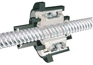
 A ball screw is a linear mechanical drive that converts rotation into linear motion and vice versa. Structurally, it is a long screw along which a ball nut moves. Inside the nuts between it internal thread and the screw threads roll the balls along a spiral path, then falling into the return channels - internal or external.
The ends of the screw are usually mounted on bearing supports, and the nut is connected to the moving unit. As the propeller rotates, the nut moves linearly along the propeller along with the payload. But there are also ball screws with a rotating nut - in this design the screw moves linearly relative to the nut.
 An ordinary screw gear consists of a screw and a nut, which have a trapezoidal thread. In such a transmission, sliding friction occurs during movement, and about 70% of the energy is dissipated in the form of heat.
Unlike a screw-nut transmission, a ball screw drive contains rolling elements (balls) that transmit mechanical energy between the nut and the screw. This provides the ball screw with significant advantages:
- Efficiency can exceed 80%
- the required power and torque of the drive motors is much less
- wear rate is minimized
- service life is much longer than that of sliding helical gears and can be determined by rolling fatigue calculations
- Less heat promotes continuous operation
 However, due to the low coefficient of friction, ball screws are susceptible to rolling, especially with large thread pitches. Therefore, in some cases, the use of a braking device is required to prevent spontaneous movement of the mechanism.
 Range of main characteristics of ball screws:
- Nominal screw diameter – from 6 to 150 mm
- Dynamic load capacity – from 1.9 to 375 kN
- Static load capacity – from 2.2 to 1250 kN
- Linear speed – up to 110 m/min.
An important parameter is also the thread pitch. The larger it is, the higher the maximum linear speed, but the lower the positioning accuracy and axial force.
We offer an extensive range of precision ball screws with rolled and ground screws. Corresponding accessories such as flange nuts and bearing supports are also available.
Rolled Ball Screws
 SKF Ball Screws are a high-performance solution for a wide range of applications where precision, reliability and value for money are particularly important.
The use of high-tech equipment in the production of rolled screws has made it possible to achieve almost the same performance and accuracy as ground ones, but at a lower cost. The standard accuracy class is G9, according to ISO 286-2:1988. From a nominal diameter of 20 mm, rolled screws from SKF meet G7 precision. Screws with G5 precision according to ISO 3408-3:2006 are available on request, corresponding to the G5 precision of ground screws for positioning.
 From SKF's wide range of precision rolled ball screws you can choose exactly what you need for your application:
- Miniature ball screws (with a nominal diameter of 6 mm, external or internal ball recirculation) – compact, efficient system drive.
- Most miniature ball screws are available in stainless steel.
- Rolled ball screws with larger nominal diameters (16 to 63 mm) are available with various types nuts, with or without axial clearance, with preload - as for normal use both in drive and in precise positioning.
- These screws offer a variety of optional accessories, such as optional nut flanges and bearing supports, to simplify assembly of the complete system.
- Rolled high pitch ball screws provide the highest linear speeds for specific applications.
- SKF also offers ball screws with rotating nuts to reduce system inertia. You can contact us for more detailed information.
 SKF offers a comprehensive range of ground ball screws for applications where high precision and rigidity are required. Since the rolling surfaces are processed with special high-precision equipment, ground ball screws are easy to adapt to almost any requirement. Standard thread accuracy is G5, G3 and G1 are available upon request.
How to make the right choice?
With SKF's wide range of ground ball screws, you are sure to find exactly what you need for your application:
- Metric and imperial
- DIN nut or cylindrical flange
- Internal or external return channels
- Flange in the middle of the nut or at one of the ends
- Nut with axial clearance, without clearance, with preload
- Single or double nut
- Standard processing of screw ends or according to customer requirements
- Custom nuts can be made to order
- Optional - shaft with shoulders cut from a metal plate
SKF Ball Screw Catalogs
 |
 |
|
To create machines with software numerical control Ball screws must be used. They differ not only appearance, but also by design. For selection a certain model You should familiarize yourself with the structure and components of the ball screw in advance.
Purpose of ball screws
All types of ball screws for CNC machines are designed to convert rotational motion into linear motion. Structurally they consist of a housing and a lead screw. They differ from each other in size and technical characteristics.
The main requirement is to minimize friction during operation. To achieve this, the surface of the components undergoes a thorough grinding process. As a result, during the movement of the lead screw there are no sharp jumps in its position relative to the housing with bearings.
Additionally, to achieve a smooth ride, not sliding friction relative to the pin and body is used, but rolling. To achieve this effect, the principle of ball bearings is used. Such a scheme increases the overload characteristics of ball screws for CNC machines and significantly increases efficiency.
Main components of ball screw:
- lead screw Designed to convert rotational motion into translational motion. A thread is formed on its surface, the main characteristic is its pitch;
- frame. As the lead screw moves, displacement occurs. Various machine components can be installed on the body: cutters, drills, etc.;
- balls and liners. Necessary for smooth movement of the housing relative to the axis of the lead screw.
Despite all the advantages of this design, CNC ball screws are used only for medium and small machines. This is due to the possibility of screw deflection when the housing is located in its middle part. Currently the maximum allowed length is 1.5 m.
The screw-nut transmission has similar properties. However, this scheme is characterized by rapid wear of components due to their constant friction with each other.
Application areas of ball screws

The relative simplicity of the design and the possibility of manufacturing a ball screw with different characteristics expands the scope of its application. Nowadays, ball screws are integral components of homemade milling machines with numerical control. Well, the scope of application is not limited to this.
Due to their versatility, ball screws can be installed not only in CNC machines. Their smooth running and virtually zero friction make them indispensable components in precision applications. measuring instruments, medical installations, in mechanical engineering. Often for bundling homemade equipment they take spare parts from these devices.
This was made possible thanks to the following properties:
- minimizing friction losses;
- high load capacity factor with small design dimensions;
- low inertia. The movement of the body occurs simultaneously with the rotation of the screw;
- no noise and smooth running.
However, the disadvantages of ball screws for CNC equipment should also be taken into account. First of all, they include complex design housings. Even if one of the components is slightly damaged, the ball screw will not be able to perform its function. There are also restrictions on the speed of rotation of the propeller. Exceeding this parameter may result in vibration.
To reduce the axial clearance, the assembly is performed with interference. To do this, balls of increased diameter or two nuts with axial displacement can be installed.
Characteristics of ball screws for CNC equipment

For selection optimal model ball screw for numerically controlled machines, please read the technical specifications. In the future, they will affect the performance of the equipment and the time of its maintenance-free operation.
The main parameter of ball screws for CNC machines is the accuracy class. It determines the degree of position error of the moving system according to the calculated characteristics. The accuracy class can be from C0 to C10. The displacement error must be given by the manufacturer, indicated in technical passport products.
| Accuracy class | C0 | C1 | C2 | C3 | C5 | C7 | C10 |
| Error at 300 µm | 3,5 | 5 | 7 | 8 | 18 | 50 | 120 |
| Error per screw revolution | 2,5 | 4 | 5 | 6 | 8 |
In addition, when choosing, you need to consider the following parameters:
- the ratio of the maximum and required motor speed;
- total thread length of the lead screw;
- average load on the entire structure;
- axial load value - preload;
- geometric dimensions - diameter of the screw and nut;
- electric motor parameters - torque, power and other characteristics.
These data must be previously calculated. It should be remembered that the actual characteristics of ball screws for CNC equipment cannot differ from the calculated ones. Otherwise, it will cause the machine to malfunction.
The number of revolutions of the balls in one circle will determine the degree of transmission of torque from the shaft to the housing. This parameter depends on the diameter of the balls, their number and the cross-section of the shaft.
Installing a ball screw on a CNC machine

After choosing the optimal model, it is necessary to think over the installation scheme of the ball screw on the CNC machine. To do this, a design drawing is first drawn up, and other components are purchased or manufactured.
When performing work, you should take into account not only specifications ball screw drive. Its main purpose is the movement of machine elements along a certain axis. Therefore, you should think in advance about attaching the processing unit to the ball screw housing for CNC machines. It is necessary to check the dimensions of the mounting holes and their location on the body. It should be remembered that any mechanical treatment of the ball screw may lead to negative changes in its characteristics.
Installation procedure in the body of a CNC machine.
- Determination of optimal technical characteristics.
- Shaft length measurement.
- Creation of a diagram for coupling the mounting part of the shaft with the motor rotor.
- Installing the gear on the machine body.
- Checking the functionality of the node.
- Connecting all main components.
After this, you can perform the first test run of the equipment. There should be no vibrations or vibrations during operation. If they appear, perform additional component calibration.
If the ball screw breaks down during operation of a CNC machine, you can repair the transmission yourself. You can order a special kit for this. You can see the specifics of the restoration work in the video:
A screw pair consists of two parts (screw and nut) connected along a screw surface. A screw pair is used to convert rotational motion into translational motion, or vice versa.
Screw pairs come with triangular, rectangular and round screw surface profiles.
In engineering, a screw surface is often called a thread. Threads with a triangular profile are divided into metric, inch, trapezoidal and thrust.
Basic geometric parameters of metric threads according to GOST 9150–81 (Fig. 5.3):
N– height of the original profile (equilateral triangle);
d, d 2 , d 1 – outer, middle and inner diameters;


Rice. 5.5. Screw pairs with rectangular and triangular threads:
c – screw, d – nut, R And d 2 – pitch and average thread diameter
step R– the distance between the nearest similar points of the contour along a line parallel to the thread axis;
profile angle = 60;
helix angle of thread (Fig. 5.4).
P
Rice. 5.6. Screw pair: v t And v a– circumferential and axial speeds of the nut; d G - outside diameter nuts; – helix angle
 or
or 
Here t– period of rotational motion.
Period of rotation of the nut


where and n– angular velocity and rotation frequency of the nut.
Nut translational speed

Friction in a screw pair
Let's consider a screw pair with a rectangular thread profile (Fig. 5.7). We assume that the axial load F A on the screw is concentrated on one turn and that the reaction of the nut is applied along the center line of the thread, i.e. d 2 .

Rice. 5.7. To determine the friction forces in a screw pair with a rectangular thread profile
The movement of a nut along a screw can be considered as the movement of a slider along an inclined plane with an angle of inclination (Fig. 5.8).
When the slider moves uniformly, the following equilibrium equation is valid:

Where F t = M/r 2 – horizontal force acting on the slider (nut), M– torque of a pair of forces applied to the nut at a distance r 2 from the screw axis in a plane perpendicular to the axis (in the horizontal plane).
From the force plan (Fig. 5.9) it is clear that the driving force F t, necessary for uniform movement of the slider up an inclined plane, is related to the magnitude of the axial force F A ratio
F t = F A tg ( + ),
and torque M pairs attached to the nut will
M = F t r 2 = F A tg ( + ) r 2 .
From the Coulomb–Amonton law it follows
F t = f N = N tg .
From the force plan we determine the friction force acting in the screw pair:

Dividing the numerator and denominator of this expression by cos and given that f= tan , we get

In a screw pair with a triangular thread, the normal force N > F A(Fig. 5.10), therefore the friction force F t more than in the screw pair with a rectangular thread profile discussed above. Respectively

Rice. 5.10. Relationships between normal and axial forces in screw pairs with triangular and rectangular thread profiles
friction angle and friction coefficient f at a screw pair with a triangular thread will be larger than a screw pair with a rectangular thread profile.
In a screw pair with a triangular thread, the friction coefficient and angle will be
 And
And  .
.
The coefficients obtained for a screw pair with a triangular thread profile f and the angle of friction are called the reduced coefficient and angle of friction.
Roller screws (gears, drives) SKF
Roller screw drives are a new stage in the development of drive technology.
The load-carrying capacity of rolling screw-nut gears almost entirely depends on the characteristics of the surfaces at the point of contact between the rolling elements and the screw: diameter, number of contact points, hardness, surface treatment to ensure accuracy and therefore uniform distribution of loads between the rolling bodies.
In ball screws, the load is transferred from the nut to the screw through balls located in the grooves of the thread. In single thread ball screws, the ball size is limited to approximately 70% of the thread pitch. In this regard, the total contact area is relatively small due to the limited number of complete turns of the balls in the nut. Show diagram.
In roller screw drives, the load is transferred through the grooved surface of all cylindrical rollers, which leads to a significant increase in the number of contact points and the total contact area relative to the ball screw. Show diagram.
Roller screw drives are characterized by:
Very high load capacity (static load up to 1500 tons, dynamic load up to 370 tons)
- Very high permissible rotation speed (for RVP with a diameter of 48 mm - 3300 rpm)
- Very high permissible accelerations (12000 rad/sq.m.)
- For a long time service even with constant work
- Highest reliability
- Good resistance to aggressive environments (dust, sand, ice)
- Good resistance to shock and vibration
- Excellent positioning repeatability (min. step 0.6 mm)
There are two types of roller screw drives.

(SR/BR/PR/HR Series) (show device) can withstand the heaviest loads in harsh environments for thousands of hours, making them suitable for applications with very high load capacity and reliability requirements. The extremely durable nut can withstand shock loads, and the roller synchronization mechanism remains reliable even at high speeds. The large thread pitch and symmetrical nut design allow linear movements with high speeds.
Planetary roller screw drives are used in broaching machines, presses, machine tools, steel production, tire production, for the automation of loading and unloading operations, military aircraft, tanks, launchers, etc.

(SV/BV/PV series) (show device) allow you to get highest precision positioning thanks to the use of fine pitch threads. The advantages of this design are minimizing the input torque and increasing resolution. They are also characterized by high rigidity.
Recirculating roller screw drives are used in laboratory and medical equipment, paper production, topographic equipment, telescopes, satellites, etc.
SKF ROLLER SCREWS PRODUCTION PROGRAM
 SRC Planetary Roller Screw Series:
increase
Cylindrical nuts with axial play
- Thread pitch from 4 to 42 mm

increase
Flange nuts with end play
- Screw diameters from 8 to 210 mm
- Thread pitch from 4 to 42 mm

increase
BRC - cylindrical nuts with eliminated axial play
- PRU - cylindrical preload nuts
- Thread pitch from 2 to 42 mm

increase
BRF - flange nuts with eliminated axial play
- PRK - preloaded flange nuts
- Screw diameters from 8 to 64 mm
- Thread pitch from 4 to 36 mm

HRC – cylindrical nuts with axial play
- HRF, HRP – flange nuts with axial play
- Screw diameters from 60 to 210 mm
- Thread pitch from 15 to 40 mm

ISR – nuts with axial play
- IBR – nuts with eliminated axial play
- Screw diameters from 12 to 120 mm
- Thread pitch from 1 to 18 mm

SRR – flange nuts with axial play
- BRR – flange nuts with eliminated axial play
- Screw diameters from 25 to 60 mm
- Thread pitch from 5 to 30 mm

increase
SVC - cylindrical nuts with axial play
- PVU – cylindrical nuts with preload
- Thread pitch from 0.6 to 5 mm

SVF - flange nuts with axial play
- PVK - preloaded flange nuts
- Screw diameters from 8 to 125 mm
- Thread pitch from 0.6 to 5 mm